 Two meter, as a VHF
band, requires a comparatively short antenna. The majority of two meter work is
local communication, and the majority of that is done via repeater on FM. Most such
communications are accomplished using vertical antennas, so I was looking for a
short vertical antenna. It also seemed that the smaller antennas made possible
by these higher frequencies might be located in my shack, and thus require only
a short cable run. As higher frequencies involve more cable loss, a short cable
run is preferred. The other side of this coin is that you want the antenna to
sit as high as possible, which often requires a cable run that is longer. The
two factors have to be weighed against each other.
Two meter, as a VHF
band, requires a comparatively short antenna. The majority of two meter work is
local communication, and the majority of that is done via repeater on FM. Most such
communications are accomplished using vertical antennas, so I was looking for a
short vertical antenna. It also seemed that the smaller antennas made possible
by these higher frequencies might be located in my shack, and thus require only
a short cable run. As higher frequencies involve more cable loss, a short cable
run is preferred. The other side of this coin is that you want the antenna to
sit as high as possible, which often requires a cable run that is longer. The
two factors have to be weighed against each other.
I considered a number of options for a vertical two meter antenna. Eventually, my choices boiled down to three: a J-pole, a ground plane, or a vertical dipole. The easiest to make would have been the vertical dipole, and for this reason it was my first consideration. A vertical dipole could have been constructed of a pair of 19" sections of copper pipe, though most are made of a pair of matching 19" sections of wire. Such an antenna would have been compact, and could easily be hidden away someplace in my shack. As a bonus, I could simply turn it sideways, and have it double as a horizontal dipole. Eventually, I decided against using such an antenna, for three reasons.
As a simple dipole, the vertical would require a balun. This was something I just didn't want to do for what was supposed to be one of my simpler antennas. In addition, the coax would need to be run horizontally to prevent the outer shield from coupling with the antenna. I also did not want to worry about having the antenna too close to the ground, which can be a problem with vertical dipoles. This last issue would seem to indicate a need for a ground plane antenna.
I already did have one ground plane antenna, for my GMRS radio, and plan two others for six meter and CB. The problem with a two meter ground plane, would be that the radials would have needed to be 19" long, making for an antenna that was 19" - 20' high and about three feet wide. This would be too big to simply squirrel away in my shack somewhere. I prefer to keep my attic free for HF antennas, and have no desire to worry about detuning the attic horizontal antennas, by introducing a UHF or VHF vertical antenna. So my two meter antenna needs to be something that can be hidden away in my shack.
This left the J-pole design. A J-pole
antenna has a rather small horizontal footprint, but is quite long for its
wavelength. Where a quarter wave ground plane on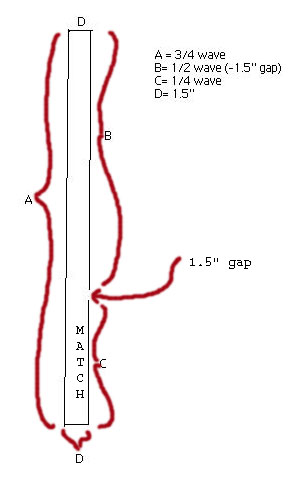 two meters would have a length
of about 19", a two meter J-pole is five feet long. Most amateur made J-poles, are constructed of copper pipe, though a
few are of aluminum, or even of wire lined fiberglass tubing. Technically, a
J-pole is an end fed half wave antenna, An end fed half wave antenna is
sometimes called a Zepp. What makes a J-pole different from a common Zepp is
that it has a quarter wave matching stub. This is a huge advantage, because it
allows the antenna to be fed by standard 50 Ohm coax cable, (often) without the need of
a balun or matcher. The regular half wave end fed antenna has an impedance of
300 ohms or so.
two meters would have a length
of about 19", a two meter J-pole is five feet long. Most amateur made J-poles, are constructed of copper pipe, though a
few are of aluminum, or even of wire lined fiberglass tubing. Technically, a
J-pole is an end fed half wave antenna, An end fed half wave antenna is
sometimes called a Zepp. What makes a J-pole different from a common Zepp is
that it has a quarter wave matching stub. This is a huge advantage, because it
allows the antenna to be fed by standard 50 Ohm coax cable, (often) without the need of
a balun or matcher. The regular half wave end fed antenna has an impedance of
300 ohms or so.
There is a variation of the J-pole called the Slim Jim. It is often made of twin lead feeder cable (better known as ladder line). What this means from a practical standpoint, is an antenna that can be hung on the wall, or hung out a window. These antennas are easy and cheap to make, and require only that a suitable length of ladder line be cut and soldered at the appropriate points. The Slim Jim is electrically a bit different than the standard J-pole. There is a second element opposite the main radiator, which makes this similar to a folded dipole, though it still uses the same J Integrated Matching (JIM) section..
In addition to it's small footprint and ease of mounting, the Slim Jim has a very low angle radiation pattern of about eight degrees. This concentrates the signal along the horizon and gives about 6 db of gain. Properly mounted, this makes for a great antenna. The downside of this is that the Slim Jim absolutely needs to be properly mounted. Improper mounting, angling or bending of the antenna could send that eight degree signal disc pointing at the sky, rather than along the ground where it is needed. Because of this, I could not mount my J-pole in the attic, even had I wished too, due to the four an a half foot height of the peak of my roof.
I live in a somewhat hilly area, which can be a problem on VHF/UHF. My second floor shack is approximately 12 feet above the ground. With the antenna tip at the ceiling, this would give the base an elevation of about fourteen feet. This isn't great, but it's not bad either. Putting it in the attic could have raised it by another ten feet or so; but my attic ceiling is not high enough to mount such an antenna without angling or folding - neither is a suitable option for a Slim Jim (though it may be possible to angle the matching stub away from the radiator - though again, neither can be folded along its own length). The antenna also needs about 20" of open space, or at any rate there should be no conductors or wiring within 20", in order to prevent coupling or detuning.
Real ham operators build their own antennas, and I was all set to do so with this Slim Jim; though I considered buying a ready made version. This is made and sold by W9TAX, and sells for around $18 by itself, or an extra $5 with a 16' coax. The quality is probably as good as I could have made it, and the trouble saved of building, testing, adjusting, and rebuilding is easily worth the cost - just a thought. For those who wish to make their own, there are instructions, as well as further details at the links below. I built my own, and saved myself about $6 - for about an afternoon's work. This came out to about 75 cents an hour.
So is this a great antenna? It is flat, unobtrusive, and cheap. Even if the 6 db gain claimed is exaggerated, it is still a very efficient and capable antenna. The table below shows a comparison of measured signal strength through various antennas at various power levels. All measurements were taken with the same field strength meter, at the same level, and the same distance from each antenna. Though an SWR reading is a handy measurement for matching the radio to the system, field strength is a far better indication of antenna efficiency.
| Antenna | TS-711 at 2 watts | HTX-200 at 200 mw | TS-711 at 25 watts |
| Duck | |||
| Big Duck | |||
| Dipole Horizontal | |||
| Dipole Vertical | |||
| Original Quarter Wave with metal ground | |||
| Slim Jim |
Construction
 There are lots of plans and suggestions for various types of Slim Jim and J-pole
antennas out there. Some are made from pipe, others from wire, and still others
from twin lead transmission line. I decided to take a different approach on
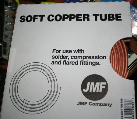
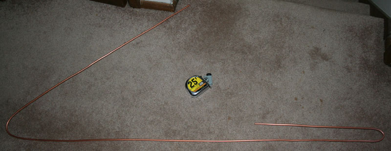
mine. It is made from soft copper tubing, of the type used for connection of
condensers and various things. This was quarter inch tubing, and is stiff enough
to hold its shape, but malleable enough to be bent by hand. One nice thing about
this material, when
There are lots of plans and suggestions for various types of Slim Jim and J-pole
antennas out there. Some are made from pipe, others from wire, and still others
from twin lead transmission line. I decided to take a different approach on
mine. It is made from soft copper tubing, of the type used for connection of
condensers and various things. This was quarter inch tubing, and is stiff enough
to hold its shape, but malleable enough to be bent by hand. One nice thing about
this material, when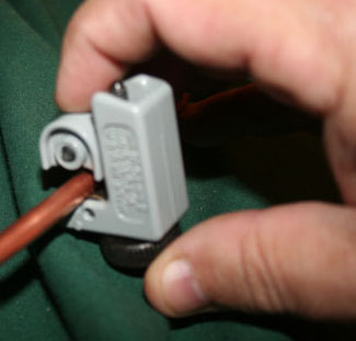 compared to standard copper pipe, is that you do not have to cut, solder and use
joints and elbows.
Soldering pipe is nothing like soldering electrical components. you do not use a
soldering iron. You use a torch. it is necessary to heat the solder, as well as
both parts to be joined.
compared to standard copper pipe, is that you do not have to cut, solder and use
joints and elbows.
Soldering pipe is nothing like soldering electrical components. you do not use a
soldering iron. You use a torch. it is necessary to heat the solder, as well as
both parts to be joined.
Quarter inch pipe should give a pretty good bandwidth, when compared with wire, though it will not be as good as that of half inch pipe. Electrical charges flow on the outer skin of a conductor, and diameter increases bandwidth. Diameter also increases power handling capacity, and I could probably use a pretty hefty linear if I ever decided I wanted to do this. AWG 2 wire has a similar diameter, and I do not even want to think about how much such wire costs. The soft copper tubing sold for around 45 cents a foot. In addition to dispensing with the need to cut and solder, bending soft tubing to the proper shape eliminates the possibility of electrical losses in the joints.
Cutting and Measuring
I cut the tubing to a length of 113", and then began to mark off the measurements, and bend the tube to shape. This might seem a bit short, but I planned on using a very short run of transmission line. The measurements should be three quarter wavelength on the long side, and a half wave and quarter wave on the short side with a gap in between. The three quarter wave side is the active radiator, the half wave is a sort of a passive radiator, used to bring the angle of radiation down, and the quarter wave sections are to match the system. With the pipe cut, it is time to measure off the bends.
Taking into consideration the variations of the design, you will find many different measurements, though all will be within a few inches of each other. The reason for this is that the various measurements, including the spacing of the elements, work together along with the air gap on the short side of the antenna. An antenna that is a bit shorter or a bit longer, will be made to work through variation of these other factors. In particular, adjustment of the connection along the matching stub can make great changes in resonance. Thus measurements are important, but not absolutely critical. Ideal gap is accepted to be an inch and a half, with the ideal separation between elements the same. With these gaps, My bends were made to the following dimensions.
Long side 56"
short side
1/2 wave 36 1/4 "
1/4 wave 18 1/4 "
For those who are purists, the most common actually recommended dimensions (by calculation) usually given are:
3/4 wave section
8415 divided by 146 = 57.63 inches
1/2 wave section 5610 divided by 146.00 = 38.42 inches
1/4 wave section 2805 divided by 146.00 = 19.21 inches
Feed point 10 to 20% of 1/4 wave = 1.9 to 3.84 inches
The gap would be about 1
1/2 to 2 inches
It should be noted that all of these dimensions are just starting points. Slim Jim antennas shorter than 56", and longer than 60" have been used with great success on two meter, after tuning and matching. Many operators mount these antennas inside of PVC pipe, which requires them to be shortened. Length and type of transmission line, as well as surroundings also play a part. In some cases, antenna design is still as much an art as a science.
Bending
The big advantage to using the soft copper tubing, is that it may be easily bent
and shaped by hand. No cutting, other than the first cut, is required, and there
is no need to solder or use joints and fittings. Bending this pipe is a process
for the patient. Though it is soft, it can still kink and twist. The tubing also
seems to grow
 harder
when it is worked. It is possible to break the tubing by bending it too much, or
by bending it back and forth. Patience is the key.
harder
when it is worked. It is possible to break the tubing by bending it too much, or
by bending it back and forth. Patience is the key.
I started with the bend of the matching stub on the short side. This was bent at a point 18.5" from the start. Again, the official measurement is 19.6"; but these things can vary with the type of material used, the feed line, and the surroundings. With the first bend started I made it an arc, rather than attempting to square it off. This is mechanically a stronger bend, and has been said to offer some advantage when compared to the squared off construction required by the use of fittings and joints. With the matching stub formed, I then formed the long side, using a measurement of 56", and once more curving the head of the bend.
I was very please to
note that, keeping the 1.5" spacing of the elements, when I made the final band,
and brought the tubing back on itself, the resulting gap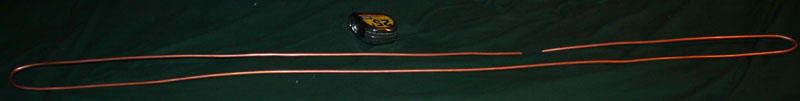 was almost exactly the 1.5" recommended. So I now had a rather strange looking
piece of tubing, bent back on itself. This tubing is stiff enough that it will
not tangle or droop; but it still needs to be reinforced to hold its shape, and
to maintain the spacing of the elements. One of the reasons that many people
make these out of ladder line, is that consistent spacing of the elements is
assured (though not at the considered ideal of 1.5").
was almost exactly the 1.5" recommended. So I now had a rather strange looking
piece of tubing, bent back on itself. This tubing is stiff enough that it will
not tangle or droop; but it still needs to be reinforced to hold its shape, and
to maintain the spacing of the elements. One of the reasons that many people
make these out of ladder line, is that consistent spacing of the elements is
assured (though not at the considered ideal of 1.5").
Reinforcing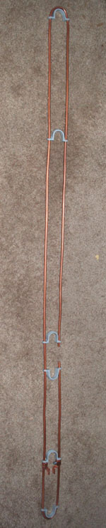
 To maintain the shape of the antenna, and hold the proper spacing between
elements, I first employed standard wood biscuits, of the type used to hold
glued joints on furniture. These are cheap, available everywhere, and easy to
work. the only problem with them is that if you are going to expose your antenna
to the elements, they will not hold up well. For antennas that will be used
outside, you will want to employ PVC, or some other weatherproof material.
Obviously, you will not want to use metal or any other substance that would
conduct.
To maintain the shape of the antenna, and hold the proper spacing between
elements, I first employed standard wood biscuits, of the type used to hold
glued joints on furniture. These are cheap, available everywhere, and easy to
work. the only problem with them is that if you are going to expose your antenna
to the elements, they will not hold up well. For antennas that will be used
outside, you will want to employ PVC, or some other weatherproof material.
Obviously, you will not want to use metal or any other substance that would
conduct.
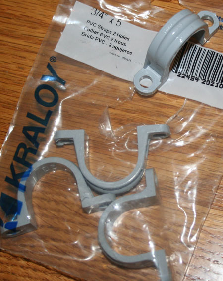
Using my drill press (a hand drill will do as well), I made quarter inch holes, spaced 1.5" apart in the biscuits, to make them into spacers which would slide over the tubing. I was then taught a lesson about tolerancing, as all of my first batch of spacers broke when they passed over the bends in the tubing. I then made a second batch, and used a Moto-tool to open up the holes to a bit over a quarter inch. They still broke. Eventually I picked up some PVC pipe straps. These worked great. The 3/4" size is ideally spaced for this, and the quarter inch holes fit the pipe perfectly. A package of five costs less than a dollar.
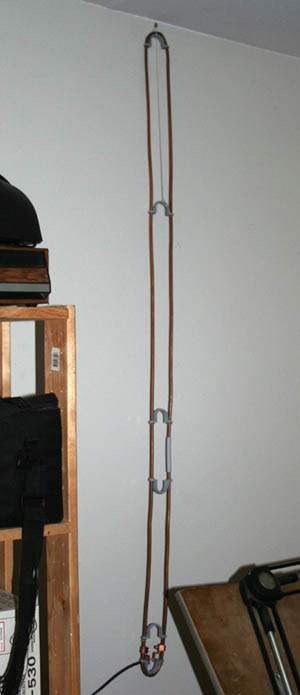
The pipe straps are semicircular pieces of PVC, with mounting flanges and quarter inch openings. They are a bit of a tight fit, but can be run up the tubing. Rather than using glue this time, I applied a bit of heat to tighten the holes. They stay in place just fine. As a bonus, the units mounted at the top and bottom help maintain the radius of the ends of the antenna. For the antenna to work correctly, the spacing between the radial, and the size of the gap must be the same.
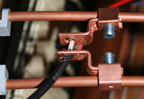
As can be seen from the photo to the right, the pipe straps work very well, look nice, and may even offer a few addition options as to the mounting of the antenna. I placed a pair on opposite sides of the 1.5" gap, and have reversed the bottom pair to make matching and tuning easier. In addition to the look and convenience factors, it is good to have a lot of open air between the elements. Any material places between or around the elements, inside of a quarter wave circle can effect resonance and SWR. Set up this way, the antenna can be hung from an attic rafter (its ultimate location), and is still thin enough with no ground plane, to be hung on a wall.
Other means can be used to reinforce and shape these antennas. Some people have simply mounted them to a 1.5" piece of PVC pipe, while others have used tie wraps and rubber spacers. One enterprising ham mounted his wire Slim Jim around a pair of yardsticks.
Tuning
This is the area that separates the men from the boys. These antennas have a nearly legendary reputation for being hard to tune. It is undeserved. What drives most amateurs crazy when tuning these things, is that there are so many variables that it is nearly impossible to give a set of measurements that will always be the same, always be reproducible, and always work for everyone. Matching is accomplished by adjusting the position of the feed line on the matching stub, at the bottom of the antenna. Where this feed must be positioned can vary depending upon the spacing of the elements, the width of the air gap, and then the usual factors such as the surroundings and the length of the elements. The position on the stub is generally said to be between 2" - 4" on a two meter antenna, which is 10% to 20% of a quarter wave.
 There are many ways to set the antenna up for matching. One of the most common
is to use alligator clips, or some such thing, to move the feed line conductors
up and down the matching stub. This is strictly a trail and error proposition,
which is why some hams hate these antennas so much. The center conductor is
connected to the long side, and the braid is connected to the short side with
the gap. Generally, once the position is determined, the fed line conductors are
soldered to the position determined to offer the best overall SWR. Sometimes
they are merely clamped, while some antenna builders will drill holes and use
mounting screws. In my own case, I used a pair of mechanical lug connectors,
designed for grounding and home wiring. These worked great, give a good strong
connection, and stay in place.
There are many ways to set the antenna up for matching. One of the most common
is to use alligator clips, or some such thing, to move the feed line conductors
up and down the matching stub. This is strictly a trail and error proposition,
which is why some hams hate these antennas so much. The center conductor is
connected to the long side, and the braid is connected to the short side with
the gap. Generally, once the position is determined, the fed line conductors are
soldered to the position determined to offer the best overall SWR. Sometimes
they are merely clamped, while some antenna builders will drill holes and use
mounting screws. In my own case, I used a pair of mechanical lug connectors,
designed for grounding and home wiring. These worked great, give a good strong
connection, and stay in place.
Though the best way to tune an antenna is always to adjust the length of the elements, setting the position of the feeder line on the matching stub lessens the precision required on element length, and saves the builder the trouble of having to disassemble the antenna and match the elements.
While an antenna analyzer makes the job faster, easier, and more precise, it can be accomplished with an SWR meter. Adjustment is a matter of moving the feed line connections up and down the matching stub, until the lowest overall SWR is achieved, or until an analyzer shows the closest resonance to that you are attempting to operate at. To save my finals, I did all such adjusting on my lowest power setting, which happens to be 2 watts. Once the sweet spot is found, the connections are tightened down, and the antenna is ready for use.
In my own case, the match was at just about the low end of the range, around two inches. This may be because my antenna was about two inches shorter than the usual dimensions given, or it may be that the connectors I used had about an inch of tail on each side. Whatever the reason, I got a great match, and have an SWR of around 1.5 on the entire two meter band. Part of this may be due to the use of tubing, instead of wire. Wider diameter conductors give wider bandwidths.
Links
| Eham review | N9TAX Slim Jim | Slim Jim | Ladder line Slim Jim |
| Wire Slim Jim | Copper Slim Jim | Pirate Slim Jim | Paraslim |
| 300 ohm Slim Jim |