| Zenith Transoceanic D7000 |
|
|
The D7000 |
|||
| The Transoceanics | Links | Log and charts | Technical manual |
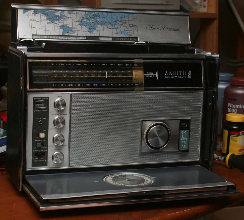
The Zenith Transoceanic radio is iconic in a number of different ways. In its day, it was a cutting edge piece of technology, a window onto the world, a mark of sophistication, a luxury item, and a bit of a status symbol. These were the most expensive and most popular portable radios of their day. A Transoceanic cost two or three weeks pay for the average worker. Yet Zenith couldn't make them fast enough.
The vast majority of these radios were probably used almost exclusively to
listen to pop stations, the news, various local music stations, and maybe the
early version of talk radio, yet the capability to tune into the world, and to
some of the low frequency utility stations was always there. These are still
very capable radios, as a look at the factory specs will show. They are
sensitive, selective, cover a wide and diverse range of frequencies, and sound great.
Zenith nicknamed these radios the Royals, and they were the top of the line of
what was then the company that was the premier producer of
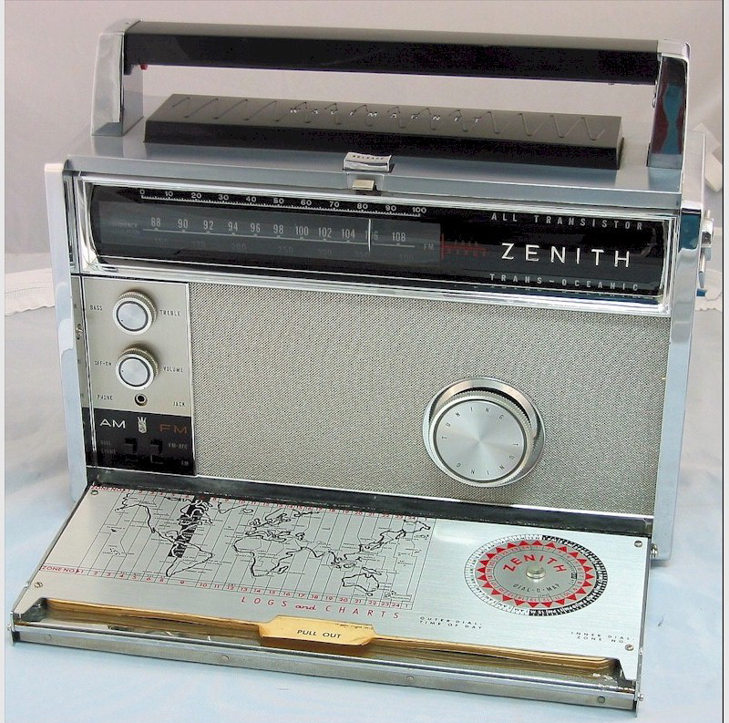
radios. This particular example is a D7000-1.
When I decided I must have an old Transoceanic radio, this was the model I had to have. Though some may argue with my choice, I believe the D7000 to be the best of one of the best lines of radios every produced. It was introduced in 1968. This was the last model entirely produced in this country, and the first to have a BFO, and to really zero in on the concept and work out every bug and annoyance of the past models. That is to say, it was the ultimate refinement of the line. It also had the best sensitivity and selectivity of the line. There was one succeeding model, the R7000, which was introduced in 1979, produced in Taiwan, and used an IC and circuit boards, dispensing with the time honored chassis and wired components.
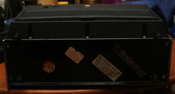
Even the bottom of this radio is interesting. There is a separate bottom panel, with padded feet. It is filled with stickers of inspectors and test labs. These radios were expensive examples of what was then modern technology. They were taken very seriously. Even the facility in which it was made was special. It was not called a factory. Transoceanic radios were produced at the Chicago Radio Lab.
The old fashioned chassis and hand wiring
of this radio give it a couple of advantages over today's more modern
production. For one thing, these old radios can be repaired. If something wears
out, breaks, or burns out, it is relatively easy to find the problem, get a new
part, and fix the radio. The transistors inside are socketed rather than
soldered, making replacement easy. Another advantage, though one that will hopefully never
be used, is that these old non-IC radios are immune to EMP. EMP is the magnetic
pulse put out by a nuclear explosion. Such a pulse destroys integrated
circuitry. The third advantage to these old radios is that they really don't
break. They are rugged, and sturdily built. 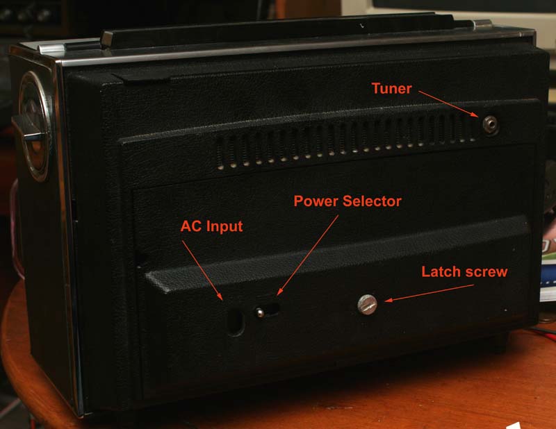
The D7000 has a very clean sound, using a two stage transistorized audio amp, that puts a half watt into a 4" x 6" speaker. This provides plenty of volume for boating, picnics, a day at the beach, or listening around the camp fire. It has a tone control, BFO, and an RF gain which can be set to automatic. It also offers a selection of narrow or wide bandwidth. This was some pretty sophisticated stuff back in its day, and the radio still holds its own even now. What it gives up to today's radios is the digital circuitry that allows for multiple memories, digital tuning, scanning, and DSP.
What you get back for not having the digital features is a very long battery life and low power consumption. Current draw is as little as 27 Ma with the volume down. Most modern radios draw anywhere from half an amp to two amps on receive. So we are talking from twenty, to eighty times the battery life here. The D7000 also has a built in power supply to run off of house current or from a 12v power source. For truly portable use, it can be run, for weeks or months at a time, from eight D cells (plus one for the lights).
So what we have here is a great sounding radio that will run from a number of different power sources with little current draw, is easy to repair and very durable. It also has great reception, being selective and sensitive, and has multiple antenna connectors for even better performance. These are all great attributes; but the real draw of the transoceanic is the multiband capability.
This is an eleven band radio. In addition to the standard AM and FM bands, this radio can receive weather broadcasts, shortwave transmissions, and even the low frequency signals sent out by navigational beacons and military systems. These include the systems designed to be used during the atmospheric chaos of nuclear war. The idea of dividing frequencies up into bands for easier handling or better performance was nothing new; but Zenith did it in a particularly effective and satisfying way.
Bandspread tuning
The Bandspread system was groundbreaking
in it's day. It was a very simple concept. Instead of trying to have
continuous unbroken coverage, or trying to
 break up
the radio spectrum into manageable bits of a certain size, Bandspread broke
them up according to use.
break up
the radio spectrum into manageable bits of a certain size, Bandspread broke
them up according to use.
Bandspread tuning was also a break from the tradition of attempting general coverage of the radio spectrum. Much of the spectrum is unused and much of what is used is of little interest to the average listener. Implementing the modern approach of less is more, the Transoceanic was limited to the frequency ranges that are actually of interest, and grouped them into discreet bands. This approach also allowed for a bit more precision, since a 12" dial that has to tune in 10 MHz will be much less precise than one that has to tune across only 4 MHz.
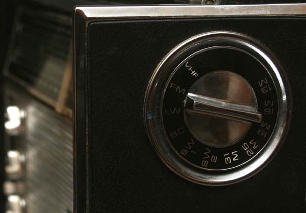
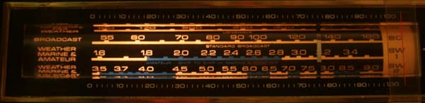
Bands are selected from a rotary
bandswitch on the side of the radio. This rotary bandswitch is a signature
feature and one of the most beloved features of the radio. Flipping the
bandswitch not only changes the frequency range, but also flips a completely
different slide rule dial into the tuning window. For radio freaks, this
combination of mechanical and electrical gadgetry is irresistible. Previous to
this, multi band radios used a single display with multiple sets of markings.
Many less expensive radios still did, even into the eighties when they were
mostly replaced with digital displays. The separate tuning dials give a feeling
of being in different radio neighborhoods, or of having multiple radios. The
drum on which these scales reside takes up quite a bit less space than if a
single large multi scale dial would have been used. The scales are printed on
translucent plastic which fits around the cylinder drum. Bulbs inside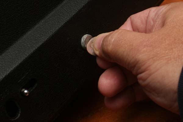 the drum backlight the scales for a nice effect.
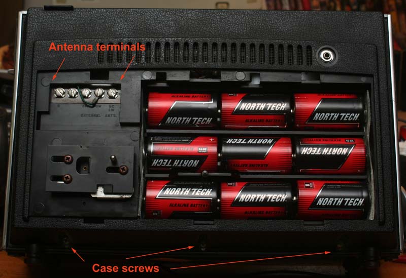
The radio is automatically switched to 115v operation by sliding a cover over the AC line input. This cover moves a slide selector switch. Some owners have advised that the radio will drift a bit when plugged into AC power, after being tuned. This can be prevented by grounding to the ground terminal next to the external antenna terminals. Grounding will also greatly increase antenna efficiency, and is a good idea for fixed location use. For portable use on batteries, the drift issue is not as pronounced, though a good ground will always improve reception.
Access to the battery compartment, antenna terminals, and switches is gained by loosening a latch screw and pivoting a rear cover off. The latch screw is designed to be turned by a coin, and is knurled on the outside. Handy.
Ordinarily the batteries ( 8 D cells for the radio, and 1 for the lights) would
be held in by plastic tubes; but they were missing from my radio when I bought
it. Capability of holding D cells, instead of the more common AA that seem to
power everything these days, means that batteries of up to 20,000 MAh may be
used. This means that at the 27 MAh draw of the Transoceanic, you could get well
over 400 hours of operation before recharge or replacement is required. It also
means easy operation off of solar power sources. Usually solar panels of
reasonable size do not have the capacity to power a modern radio. As of this
writing, you
 can
pick up a solar cell measuring 4"x11" (just about the measurements of the top of
this radio) that will put out 12v at 120 Ma. This is about an eighth of an amp,
which is inadequate for anything other than maybe topping off batteries on one
of today's digital wonders; but is more than enough for the 27 Ma draw of the
Transoceanic. This is true even on a cloudy day which can cut a solar cell's
power to less than half.
can
pick up a solar cell measuring 4"x11" (just about the measurements of the top of
this radio) that will put out 12v at 120 Ma. This is about an eighth of an amp,
which is inadequate for anything other than maybe topping off batteries on one
of today's digital wonders; but is more than enough for the 27 Ma draw of the
Transoceanic. This is true even on a cloudy day which can cut a solar cell's
power to less than half.
A Transoceanic with a full load of batteries is a heavy item to lug around. The chassis and case make for a pretty sturdy radio, and the front covers fold up protectively to prevent damage to the front face and speaker grill during transport. The large battery compartment suggests several different options ranging from rechargeable D Cells through various gel cells and other battery packs. All will fit. As of this writing, a local marine dealer is selling a 12v gel cell with a capacity of 45000 Mah. The battery is small enough to fit into the compartment, though I would have to modify the shape of the compartment somewhat. Still, it's a thought. I could use the solar cell mentioned above to keep the battery topped off. Such a system could keep this radio powered up independently of any external sources for years.
Antennas and antenna options
Like any radio, particularly one that operates on lower frequencies, the Transoceanic benefits greatly from a good external antenna. Even a plain old twenty or thirty foot long piece of wire can make a world of difference. This is especially true on the SW and LW bands. If you want to get really fancy, a balun along with a good SW antenna, or a nice multi element dipole will make this radio as capable as anything out there.
As it comes from the factory, the Transoceanic has an internal wire-wound ferrite rod which it calls a Wavemagnet, and a standard telescoping rod which it calls the Waverod. These two antennas are good enough for casual listening and are provided because you have to have some sort of antenna on a portable radio; but they are far from ideal.
 On older Transoceanics,
the wavemagnet used to sit in its own special molding on top of the radio. In
some models it was removable, and could be mounted externally to improve
reception. Technically, the Wavemagnet is a magnetic loop antenna. A magnetic
loop differs from a normal loop in that it is less than a tenth of a wavelength
in size. This particular type of magnetic loop is commonly called a loopstick,
due to its construction. A loopstick is made by wrapping a number of turns of
Litz wire around a ferrite rod, to create a very small loop antenna surrounding
a ferrite core.
On older Transoceanics,
the wavemagnet used to sit in its own special molding on top of the radio. In
some models it was removable, and could be mounted externally to improve
reception. Technically, the Wavemagnet is a magnetic loop antenna. A magnetic
loop differs from a normal loop in that it is less than a tenth of a wavelength
in size. This particular type of magnetic loop is commonly called a loopstick,
due to its construction. A loopstick is made by wrapping a number of turns of
Litz wire around a ferrite rod, to create a very small loop antenna surrounding
a ferrite core.
Such an antenna is extremely inefficient, which is why an external antenna can make such large improvements on radio performance. The advantage of the loopstick is that it is physically very small for the bands it receives, and its magnetic properties make it very resistant to local noise and interference.
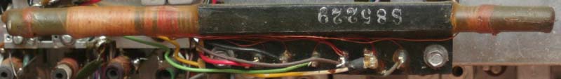
A photo of the internal loopstick is above. Notice that it has two
unevenly sized sides. This is because the sides are wound for two different
bands, essentially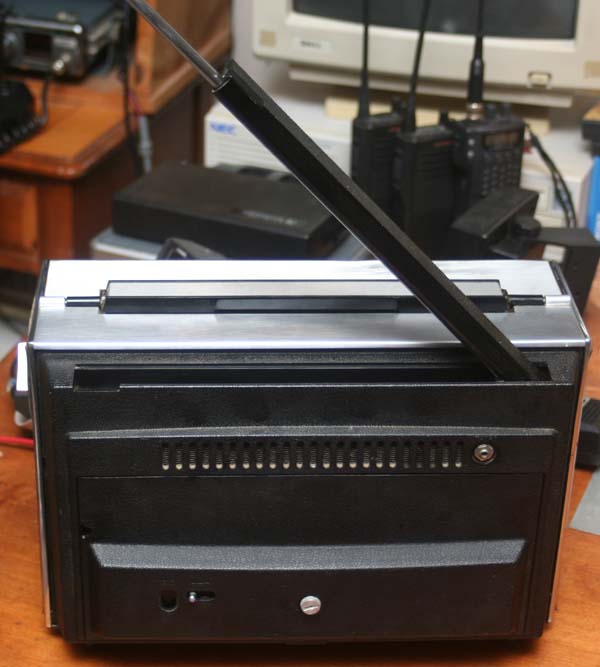 making this a double loop antenna. The smaller side is for
AM broadcast band reception (BC), while the longer side of for LW reception.
Though these are extremely inefficient antennas, mostly due to their small size,
they tend to be good enough for AM and most LW work due to the large amount of
power put out by most AM stations, and the large amount of atmospheric noise
which makes extreme sensitivity on these low frequency bands less of an
advantage than at higher frequencies. You may also note in the spec chart below,
that AM (BC), and LW are the least sensitive portions of this radio's receiver -
by a pretty large margin. This is by design, because the background noise is so
high at these low frequencies that increases sensitivity would actually decrease
performance.
making this a double loop antenna. The smaller side is for
AM broadcast band reception (BC), while the longer side of for LW reception.
Though these are extremely inefficient antennas, mostly due to their small size,
they tend to be good enough for AM and most LW work due to the large amount of
power put out by most AM stations, and the large amount of atmospheric noise
which makes extreme sensitivity on these low frequency bands less of an
advantage than at higher frequencies. You may also note in the spec chart below,
that AM (BC), and LW are the least sensitive portions of this radio's receiver -
by a pretty large margin. This is by design, because the background noise is so
high at these low frequencies that increases sensitivity would actually decrease
performance.
As it comes from the factory, The Transoceanic also has an extensible rod antenna which it calls the Waverod. This is used for SW/FM reception, and like the Wavemagnet antenna it is pretty inefficient. The Waverod is connected to a special terminal that routes it to both the FM and SW portions of the radio. The antenna extends to 53". Its mount has locking positions at 45 degrees and 90 degrees. When not being used it folds down flat within the back of the radio.
Eventually you will come to a point where you will want better performance from the radio, and will consider an external antenna. This isn't such a big deal for AM and FM which will mostly be local stations; but for listening to a SW station on another continent, a better antenna can be a real help.
The most improvement for the least amount of effort and money is to attach a 50' to 70' long wire to the SW terminal on the back of the radio. This is commonly known as a long-wire or random wire antenna, though it is not truly of random length. A 50' wire is resonant on 31 meters, and a 70' wire is resonant on 49 meters. For even better performance, you can create a multi-element antenna, popularly known as a fan dipole, with elements cut for resonance on your favorite bands. There is even a small notch on the left hand side of the back cover to run the external antenna wire out. The antenna terminals are accessed by removing the back cover. If you run a single long wire antenna, best results will be obtained by also attaching the ground terminal to a good ground.
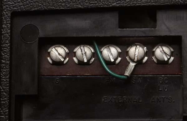
The five terminals inside the back cover are for the various bands. Recall that this is actually three radio receivers built into one case and sharing some components. The left terminal is for ground, the one unmarked terminal next to it is for the Waverod antenna. This connects the Waverod to the FM and SW receivers. The other terminals are marked FM, SW, BC/LW.
These are 300 ohm balanced antenna connections, which means you will need to connect to an earth ground, or use a dipole antenna and connect one side of the dipole to the ground terminal, and the other side to the terminal for the band you are using. As this radio will never be used to transmit, you don't strictly need to have the ground attached, and can use a simple long wire; but proper grounding will greatly improve performance and lessen noise.
If you have the room, the best antenna is probably a mutli-element dipole (usually five element pairs) with the longest element pair being 144' long. I am working on a multi element, folded dipole cut for the SW bands; but for now have a temporary long wire antenna. It is about 50' long, and I had to bend it in some places, so the run is not completely straight. Even so, the difference is striking. It is so striking that I may not bother to make that multi element dipole.
I generally test antennas by checking reception on WWV. This is the United States time and frequency standard. WWV broadcasts out of Ft. Collins Colorado. For those who are not familiar with it, WWV transmits continuously at 2.5 MHz, 5 MHz, 10 MHz, 15 MHZ, and 20 MHz. The station puts out 2.5 KW on 2.5 MHz and 20 MHz, and 10 KW on the rest. Ft. Collins is about a thousand miles away from where I live, making this a reasonable test of radio reception and propagation. With the normal antennas, WWV could just barely and intermittently be detected on 2.5 MHz. It was a bit better on 5 MHz, but still rather faint. I could not raise it on 10 MHz, or 15 MHz at all.
With the new wire in place, WWV was as clear as any local station on 2.5 MHz and 5 MHz, and was detectable on 10 MHz, and15 MHz, though not strong. This was during the very early morning hours when propagation around 10 MHz and 15 MHz is not at its best, so it may not have been the radio. I also noticed with the new antenna that numerous stations suddenly appeared, particularly on the lower frequency bands, which I had been unable to find before. Switching the same antenna over to my trusty Kenwood TS-440 got similar results. As a matter of fact, the TS-440 with its more sophisticated digital circuitry and newer design could not detect even the faint signals on 10 MHz and 15 MHz that the Zenith had barely heard.
Features
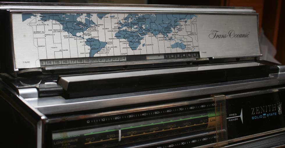
Other than the bandswitch and multiple frequency scale drum, the most remembered and beloved feature of these radios is the world time map. This started out as a simple world map with a circular calculator that could be rotated to set to your current time, and would then indicate the time in various parts of the world. By the introduction of the D7000 this had evolved into a film strip adjustable by a pair of circular knobs. it is a neat looking feature and somewhat handy, though Daylight savings can sometimes mess up the time a bit. The map and time zone clock are built into the top section of the protective cover. When not in use it folds down to protect the tuning dial.
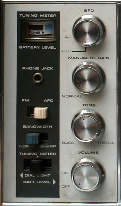
The Transoceanic has what can only be called a control panel. It is to left of the speaker on the front surface of the radio. All of the major controls are here, except the bandswitch, and tuning dial. A combination tuning meter and battery meter sits at the top of the panel. Just below this is a standard 1/8" audio jack. Another line out, marked tuner, is located on the back of the radio.
Dials
BFO: For those not familiar with it, a BFO (Beat Frequency Oscillator) permits legible reception of of SSB signals, and renders Morse Code as the classic beeps. It is adjustable to fine tune for variations in the sidebands. On CB radios, this dial is called a clarifier.
RF Gain: When set to Normal, an auto gain circuit is used. When switched to manual, this control will attenuate incoming signals. This is handy when powerful signals on nearby frequencies are causing interference, or when the receiver's front end is in danger of being overloaded. So this control allows for a relatively sensitive receiver that can be toned down in high signal areas.
Tone: Pretty obvious what this one does. Basically it alternates between a high frequency and low frequency filter. This can be handy with signals that are too sharp or too muddy.
Volume: Another pretty obvious control. Louder or softer. This controls the radio's half watt audio amp. It also acts as the on/off switch.
Switches
AFC: This cuts in the AFC on FM. AFC locks to a signal even if the frequency should drift
Bandwidth: This switches from a wide to narrow signal bandwidth. This can be handy when zeroing in on a weak signal, or broadening out to try and smooth a strong signal.
Meter/Light: In normal position, this leaves the tuning meter active. When switched to one side, it turns on the dial light. When switched to the other side it shows battery level.
This is a pretty simple layout by today's standards; but allows you to control everything that needs controlling. The BFO is a particularly good feature to have, particularly in a radio made during the 60's when there was relatively little sideband activity. With a BFO you are able to precisely tune to either the upper or lower sideband, dispensing with the need to have an USB/LSB switch. Though this pre digital radio has nothing like today's modern DSP (Digital Signal Processing), it is amazing what a combination of the RF gain, tone, and bandwidth controls can do.
The tuning dial is not part of this control panel, and sits off by itself to the right of the speaker. The bandswitch is on the right hand side of the radio. There is also an internal switch that can only be accessed by removing the back. This switch sets the internal transformer for either 115v or 230v, and comes set from the factory at 115v.
Another feature fondly remembered is the little desk that the bottom cover of
the radio opens into. On earlier models, this contained the Dial-O-Map, which
was a time converter and world map. An improved version of this is now contained
within the top cover, as noted above. In the D7000, the lower cover has a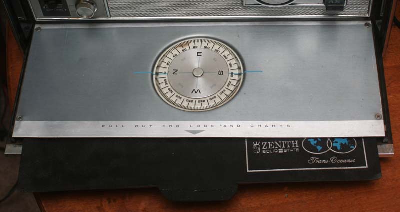 compass rose, and still has a small compartment which contains a log book,
station listings (accurate as of the late sixties), and a brief summary of the
instructions. The bottom cover is designed to open up, and then tuck partially
into the bottom of the radio. It is also completely separate from the top cover.
This is a huge improvement on the original design, which had a two piece hinged
bottom cover that, when closed and latched, served to enclose the entire front
of the radio. This original design was delicate and cumbersome, and these covers
were always getting bent or broken. The new covers are much batter, look good,
and still hold the old log books. The compass rose is moveable, but pretty
useless. Still, it's a nice decorative touch.
compass rose, and still has a small compartment which contains a log book,
station listings (accurate as of the late sixties), and a brief summary of the
instructions. The bottom cover is designed to open up, and then tuck partially
into the bottom of the radio. It is also completely separate from the top cover.
This is a huge improvement on the original design, which had a two piece hinged
bottom cover that, when closed and latched, served to enclose the entire front
of the radio. This original design was delicate and cumbersome, and these covers
were always getting bent or broken. The new covers are much batter, look good,
and still hold the old log books. The compass rose is moveable, but pretty
useless. Still, it's a nice decorative touch.
Be Prepared
Though there was nothing like the
survivalists movement of the eighties, or the prepper movement of today, back
when these radios were produced, you have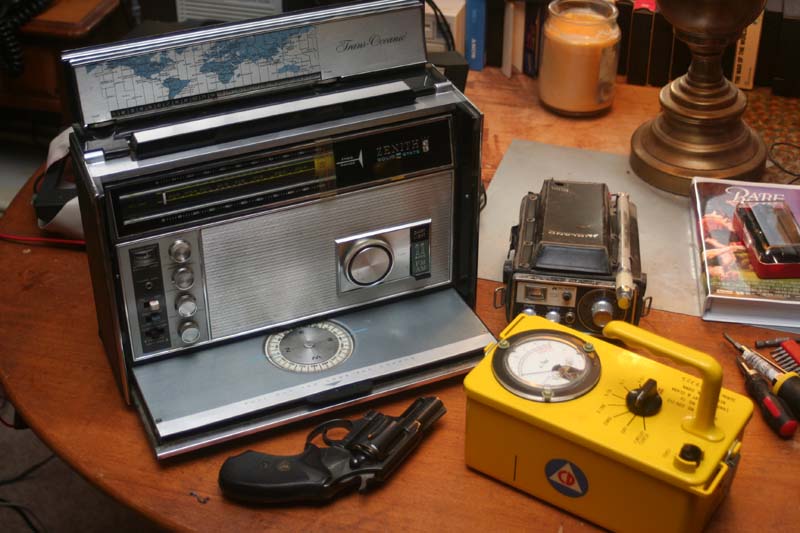 to wonder how many of them were
sitting down in basement fallout shelters, or stored carefully in cabins, car
trunks, or out of the way places, with perhaps a little
food and water. These were the days of Conelrad, duck and cover, civil defense,
and the Cold War. Even discounting the nuclear attack that fortunately never
came, a radio like this would have been a natural companion for a natural
disaster, power outage, or one of the many civil disturbances that had become a
big feature of the sixties.
to wonder how many of them were
sitting down in basement fallout shelters, or stored carefully in cabins, car
trunks, or out of the way places, with perhaps a little
food and water. These were the days of Conelrad, duck and cover, civil defense,
and the Cold War. Even discounting the nuclear attack that fortunately never
came, a radio like this would have been a natural companion for a natural
disaster, power outage, or one of the many civil disturbances that had become a
big feature of the sixties.
Local stations could be tuned in, of course, but so could distant stations in other areas or countries, ham operators, military broadcasters, and the emergency stations. A connection like this to the outside world could be a very comforting thing, especially with a battery life of over 400 hours.
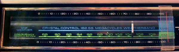
The Bands
| Band | Dial | Notes |
|
VHF |
Weather stations. On this model there is one crystal controlled frequency. Newer models have as many as five, and the band is tunable. |
|
|
FM |
Standard FM broadcast band 88 MHz to 108 MHz. |
|
|
LW |
|
|
|
BC |
Standard AM broadcast, though there seems to be something special about listening to them on this radio. |
|
|
SW1 |
The lowest of the Shortwave bands, which includes the amateur 160 meter band. Technically, most of this band is MW rather than SW. This includes the traditional maritime and nautical frequencies. These are pretty dependable ground wave frequencies. WWV can be found here at 2.5 MHz |
|
|
SW2 |
Similar propagation to above with perhaps a bit longer range. These have a mixture of amateur and maritime frequencies. Good communications to ranges of 1000 - 1500 miles. Not quite as noisy as lower frequencies. The very popular 40 meter ham band is here at 7 MHz. WWV can be found here at 5 MHz. |
|
|
31 meters |
Busiest and most popular shortwave bands are here. This band is capable of worldwide communication, but only at certain times of the day or under the right conditions. One of the most dependable Skywave bands. WWV can be found here at 10 MHz. |
|
|
25 |
Similar to above. Relatively good range through skywave propagation at appropriate times of day. Worldwide communication possible with pretty good consistency. |
|
|
19 |
More dependant on conditions than bands listed above; but capable of better, longer range contact when the band is open. Frequencies this high become less consistent than bands listed above. When the band is open, it is only during daylight hours. |
|
|
16 |
Similar to above, only more so. Quite dependant on ionospheric and atmospheric conditions, but very long range with excellent clarity when things are working right. Only open during the day, if then. |
|
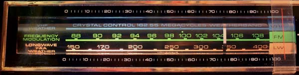
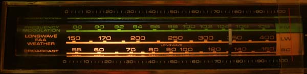 Long Wave VLF broadcasts. Mostly nav beacons, military radio, and
utility stations for airports. Also fax (and marine fax) services and
RTTY down here. It's a pretty interesting place, and a group of enthusiasts
calling themselves low-fers, spend lots of time down here. Usually it's
beeps or Morse code some ratchet sounds and
the occasional serving of hash.
Long Wave VLF broadcasts. Mostly nav beacons, military radio, and
utility stations for airports. Also fax (and marine fax) services and
RTTY down here. It's a pretty interesting place, and a group of enthusiasts
calling themselves low-fers, spend lots of time down here. Usually it's
beeps or Morse code some ratchet sounds and
the occasional serving of hash. 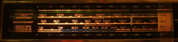
| Zenith Transoceanic D700 | ||||
| Power | AC = 113/230 V @50/60 Hz selectable | Consumption | 27 Ma | |
| DC = 13.8 v nominal/9 x 1.5 v D cell batteries | ||||
| Power output | 500 Mw | Speaker | 4 x 6 22 ohm | |
| Antennas | BC/LW = wavemagnet ferrite coil | SW/FM = Waverod telescoping | VHF = internal coil | |
| Misc. | Headphone and speaker jacks (8 ohm); external antenna terminals; AC connector; Tuner connector | |||
| Dimensions | 13.8" x 10.2" x 6.2" | Weight | 13.25 pounds | |
| Band | Frequency | Meters | Sensativity | |
| VHF | 161 - 164 MHz | 1.83 - 1.86 | 3 Mv | |
| FM | 88 - 108 MHz | 3.4 - 2.8 | 3 Mv | |
| LW | 150 KHz - 400 Khz | 2000 - 750 | 175 Mv | |
| BC (AM) | 540 KHz - 1.6 MHz | 555 - 188 | 50 Mv | |
| SW1 | 1.6 MHz - 3.5 MHz | 188 - 85 | 3 Mv | |
| SW2 | 3.5 MHz - 9 MHz | 85 - 33 | 4 Mv | |
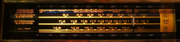
| 31 | 9.4 MHz - 10.1 MHz | 31 | 2 Mv | |
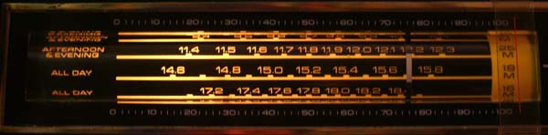
| 25 | 11.4 MHz - 12.3 MHz | 25 | 2 Mv | |
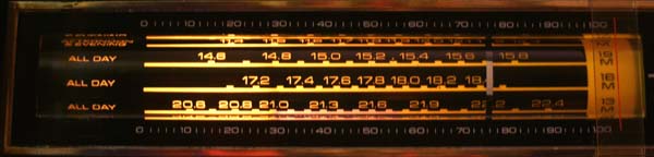
| 19 | 14.6 MHz - 15.8 MHz | 19 | 2 Mv | |
| 16 | 17.1 MHZ - 18.5 MHz | 16 | 3 Mv | |
| 13 | 10.6 MHz - 22.4 MHz | 13 | 3 Mv | |
 These are wonderful old radios;
but the most recent examples are over forty years old. As such, the acquisition
of a Transoceanic should be considered as just the beginning. It might help to
think of this is a Transoceanic radio kit. It is also helpful to recall that
this is not a single radio. It is a collection of three radios in one case. The
SW, FM, and VHF receivers are completely separate radios, which happen to share
the same speaker, power supply, and tuning dial. The good news is that because
these are forty year old radios, they were designed to be repaired, and are
straightforward and relatively easy to work on.
These are wonderful old radios;
but the most recent examples are over forty years old. As such, the acquisition
of a Transoceanic should be considered as just the beginning. It might help to
think of this is a Transoceanic radio kit. It is also helpful to recall that
this is not a single radio. It is a collection of three radios in one case. The
SW, FM, and VHF receivers are completely separate radios, which happen to share
the same speaker, power supply, and tuning dial. The good news is that because
these are forty year old radios, they were designed to be repaired, and are
straightforward and relatively easy to work on. My particular example was purchased locally for $100. This first thing I noticed was that it was dirty and smelled quite strongly of cigarette smoke. In general it seemed in good shape. Some blue oxide by one of the bottom screws indicated the batteries had been left in long enough to leak; but examination of the battery box showed little damage, other than a white flaky residue on the shields by the terminals. Fortunately, this radio is built in a way so that a leaking battery will not damage any internal components. I was also pleased to discover that the radio worked off of batteries, despite the evidence of leakage. On the good side, the antenna was not bent or broken, the case was not scratched to any degree, the dial was clear, and all the moving parts worked without binding or excessive play. I considered myself lucky as these are the hardest parts of a Transoceanic to be found in good condition. The lights were all burned out; but this is almost to be expected. One of the metal trim inserts on the top of the case was a bit warped.
Reception was fair. The weather band worked perfectly, on it's single station. FM worked perfectly as well. I then tested the unit on SW. Extending the antenna, I was able to get numerous stations, mostly in Spanish, on the 31 meter band. I was also able to get WWV at 10MHz and 15MHz, though in both instances it sounded muddy. Things were improved a bit when I noticed the RF gain was turned down, and the BFO was on. Resetting this for better sensitivity made some improvement, but reception was still not all it could be. I also noticed the scale was off by a small amount.
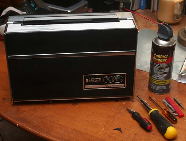
Upon initial disassembly, I noticed that one of the wires was not properly connected to the antenna. Before attempting to connect anything, or make any changes beyond a good cleaning, I searched the net for schematics, manuals, and service books for the radio. I then set about making sure I had the proper tools for the job. these included:
-
Rags
-
Alcohol
-
Contact cleaner
-
Regular cleaner
-
Screwdriver with bits
Initial Cleaning
For a start, I just
wanted to clean the old girl up, and get her in decent general condition. I
attempted no repairs on this first pass. If you decide to attempt disassembly
and cleaning, please download the service manual,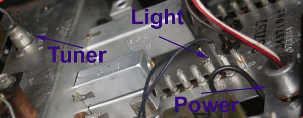 which I have a link to at the
top of the page. Without this manual, disassembly is very difficult. You begin
with removal of the battery cover on the back. This is simple enough, and requires
the loosening of a single thumbwheel style screw, as shown above. Strictly speaking, you can
probably leave it on; but a good cleaning would include a cleaning of the
battery compartment.
which I have a link to at the
top of the page. Without this manual, disassembly is very difficult. You begin
with removal of the battery cover on the back. This is simple enough, and requires
the loosening of a single thumbwheel style screw, as shown above. Strictly speaking, you can
probably leave it on; but a good cleaning would include a cleaning of the
battery compartment.
Next comes the removal of the back itself. This is done by removing three screws from the bottom, and then lifting the bottom and pivoting off. A photo of the back shown above has these screws indicated by arrows.
Once the back is detached, you must
remove a lower, three pin power plug, and an upper tuner plug. Firmly grasp the
connectors and pull straight out. Do not pull out by the wires. Removal of these
connectors will allow
for complete removal of the back.
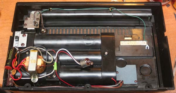
Within the back, the transformer and power supply components may be removed by loosening three screws that hold them in place. There is also a transformer held in place by a pair of screws, and an AC/DC switch under a dust cover. With all of these removed, the back panels of the radio may be cleaned with (*GASP*) soap and water. A photo of the inside of the back is to the left. Note the RCA jack and cord to the upper left, and the three socket power plug just below the center of the photo.
Now for the hard
part. All of the control knobs must be removed before final disassembly can be
accomplished. Pulling the knobs off the front face requires courage, since they
have been on for forty years or so. There are the three smaller knobs
controlling volume, tone, and BFO, as well as the large tuning knob. These must
be gently, but firmly pulled out. But worse is yet to come. The most difficult
part of disassembly is the removal of the band switch from the side of the
radio. This must be removed before the chassis can be pulled out of the case.
Before the band switch can be removed, a set screw holding it in place must be
loosened. Doing so requires a long shank screwdriver and a hex bit. It
also requires patience. The hex screw is set in a rather deep and narrow opening
in the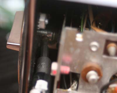 radio. You will need to set the band switch to the 19m position to see the set
screw. The good news is you do not have to completely remove it. Loosening it a
bit should allow the band switch knob to pull right out.
radio. You will need to set the band switch to the 19m position to see the set
screw. The good news is you do not have to completely remove it. Loosening it a
bit should allow the band switch knob to pull right out.
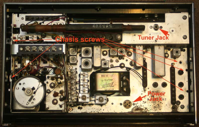
With the band switch knob removed, and all the other knobs pulled off the front face of the radio, the chassis may be pulled straight out after removal of the five screws holding it to the front of the case. Three of these screws are attached to an L bracket which may also be removed. Please note that before chassis removal can be accomplished, you will need to be careful to unplug the speaker leads, and the power leads to the chart light. The location of the screws is shown in the photo below. Also shown are the locations of the power and tuner jacks that must be unplugged before completely removing the back. The side panels and bottom panel of the case may also be separated, though I saw no reason to do so.
The speaker is held to the front grill by four screws. Removing the speaker allows access to a foam insert that has turned to dust or something even worse over that last forty or so years. Removing it immediately improves the sound of the radio. It was probably originally put there as some sort of dust barrier, or perhaps to deepen the sound of the speaker a bit. If you are a purist, you can probably find a similar material at a fabric store. I didn't bother; but may do so at a later date. As a matter of fact, I have noticed a bit of a vibration buzz in the radio. So I will need to either get some rubber stand offs for the speaker or a new foam insert.
With the chassis and
speaker out, you can give the inside of the case a good cleaning. I was a bit
more careful with the chassis itself. I started out with blasts of canned air,
and then sprayed it down pretty good with contact
cleaner. I then let it dry over night. In particular, I concentrated
 on the areas around the transistors.
These are socketed units, and along with the coils are the main components
showing in the photo to the left. I have read recommendations to bounce the
transistors in their sockets while spraying with contact cleaner, in order to
clean the connections. I lack courage to perform this task, and the regular
cleaning seemed to work well enough.
on the areas around the transistors.
These are socketed units, and along with the coils are the main components
showing in the photo to the left. I have read recommendations to bounce the
transistors in their sockets while spraying with contact cleaner, in order to
clean the connections. I lack courage to perform this task, and the regular
cleaning seemed to work well enough.
Other than the foam insert, I noticed nothing that needed removal or replacement. So I put the radio back together, and hoped for the best. When I first put the radio back together, it would not work on AC and I had no batteries to test it. With batteries installed, the radio works perfectly, and the AC problem seems to have fixed itself. In retrospect, I probably had the voltage switch set wrong, which causes a thermal switch to open.
Reassembly is essentially the reverse of disassembly, with the major headache again being the set screw for the band switch knob. With everything put back together and the radio working better than when I got it, I have a bit more confidence about disassembly. At some future date I will isolate the speaker from the case, using rubber stand offs, and will do a more thorough cleaning of the transistor contacts. I may also attempt an alignment, though the radio is presently fairly accurate on frequency.
| I view of the chassis from the top. From here you can see the Wavemagnet antenna, and the drum upon which the plastic sheet containing the band dials is printed. You can also see the brutally complicated mechanics and electrics of the band switch to the left of the photo. | 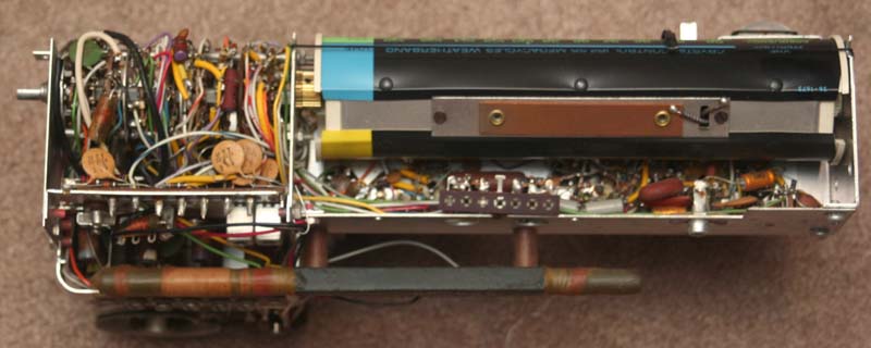 |
| The back of the chassis, which is recognizable from the disassembly photo above. Also visible are transistors, coils, a part of the tuning assembly, and the Wavemagnet antenna. The little metal box just to the right of the wheel in the lower left of the photo, is the FM radio unit. | 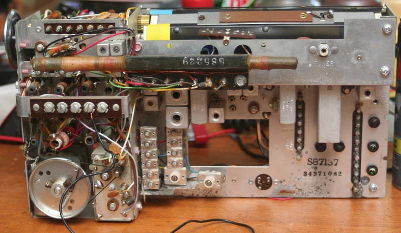 |
| The front of the chassis, including the drum with the various band dials. Also visible are the switches and meter for the control panel. To the right can be seen part of the rather complicated structure used by the bandswitch. | 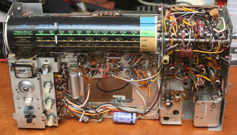 |
| The inside of the case, with everything except the speaker removed. I love the Zenith logo on the speaker, put there even though ordinarily no one will ever see it. | 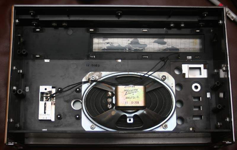 |
Shortwave Listening
At one time, the whole world was on shortwave. It was the best way to keep up with what was going on and get a window on the rest of the planet. Now the Internet has largely taken its place, but not completely. There is still quite a bit of activity on shortwave. These bands do have worldwide reach, and are international in a way that the Internet still is not.
The nature of the shortwave and longwave bands was briefly given above; but there is so much more to it. This is why there are so many different bands and so many different types of radios. The whole science and trick of long distance radio is that there are two types of radio propagation. You have skywaves, and groundwaves. This is the cause of several different contradictions when it comes to radio propagation. There are also several different regions of the atmosphere which affect skywaves, and these tend to change with sunspot conditions, time of day, and season.
As a rule, at lower frequencies, the lower the frequency the better the groundwave range and the longer the range. Some of the really low frequencies are good for regular worldwide communications, and some can even even communicate under water. Groundwave communication is dependable and consistent within its range; but starts to get useless for daytime communications over long distances around the AM radio frequencies.
At shortwave frequencies groundwave propagation is useless; but shortwaves can bounce off of certain layers in the upper atmosphere to produce skywaves. Different layers are active at different times, and reflect different frequencies. A frequency that is too high will tend to pass through the atmosphere and go off into space. A frequency that is too low will tend to get absorbed by one or another of the charged layers. A frequency that is just right will be reflected off a layer like a light beam off a mirror.
AM radio is known for its ability to be heard thousands of miles away at night, but not during the day. Here's why. The main charged layers are the D, E and F (sometimes divided into F1 and F2) layers. They are lettered according to their height, so the D is lowest, and the F is highest. All of these layers are electrically charged by the action of sunlight, solar wind, and various forms of radiation from the Sun. This makes them react in various ways with radio waves. During the day, the D layer absorbs AM band radio, so that skywave is impossible. At night, due to its relative nearness to Earth, the D layer loses its charge and disappears. The AM frequency waves are then able to go higher until they hit the F layer which reflects them back to Earth. This is why certain frequencies work better at night.
You will notice on the chart below that a number of frequency segments are very good at night, but terrible during the day. The reason given above, involving the D layer is why. What's strange here is that somewhere around 25 meters, the situation reverses, and you have frequencies that are very good during the day, but terrible at night. This is because these are able to penetrate to the reflective F layer during the day; but are able to penetrate past it at night, when its reflectivity goes down. All of the ionosphere layers are more strongly charged during the day. At night, the D and E layers nearly go away, allowing penetration fo radio waves to the higher level F layer. The problem here is the the F layer is not as strong at night, so that some waves which might be reflected during the day, are allowed off into space at night.
As the frequencies increase, the "penetrating" power of the frequency increases and it can get higher into the F layer of the ionosphere before being reflected back. The higher it goes, the further away it will come down, increasing range. The problem is that eventually, a frequency will be high enough to penetrate completely and leave the Earth. The frequency at which this happens is the MUF (Maximum usable frequency) and it varies with sunspot activity, time of day, season, and other factors. So as a general rule, the MUF will also be the frequency that gives the best range.
One of the reasons that the 31 meter band is so popular is that it hits a sweet spot between the various factors that affect propagation. It has a good range of around 2000 miles during daytime conditions, which increases to around 4000 miles at night. Higher frequencies tend to perform poorly at night (though they can far exceed 31 meters during the day - depending upon conditions), while lower frequencies are not dependable during the day (though they will have longer range at night).
So now that you know how the frequencies propagate, you might wander why bother. What is there to hear out there these days? Today it is mostly government stations, religious stations looking for a voice, and new services. Yet there are also the little treasures out there. There are a lot of far away places that have underdeveloped infrastructures and find SW the best choice for covering their area. This will tend to be Africa, parts of the mid-east, and certain sections of Asia. It might also include a lot of tropical areas and island nations. This will be local news, features, and interests, and is generally not meant for worldwide listening. Interesting.
There is still lots of interesting stuff to hear out there. Try looking at http://www.dxing.com/tuning.htm
| The Shortwave Bands | Zenith Frequency Coverage (MHz) | |||||||||
|---|---|---|---|---|---|---|---|---|---|---|
| Meter Band | Frequency Range | Day Range | Night Range | Remarks | R-1000 | R-3000 | RD-7000Y | R-7000 | ||
| 120 m | 2300–2495 kHz | 75 miles | 3000 miles | tropic band | LW | .15 - .4 | .15 - .4 | .17 - .45 | ||
| 90 m | 3200 – 3400 kHz | 100 miles | 3000 miles | tropic band | MW | .54 - 1.6 | .54 - 1.6 | .54 - 1.6 | ||
| 75 m | 3900 – 4000 kHz | 100 miles | 3000 miles | tropic band shared with amateur 80m | SW | 2 - 4 | 1.6 - 3.5 | 1.8 - 4 | ||
| 60 m | 4750 – 5060 kHz | 3000 miles | tropic band | SW | 4 - 9 | 3.5 - 9 | 4 - 7.5 | |||
| 49 m | 5900 – 6200 kHz | 3000 miles | SW | 9.4 - 10.1 | 9.4 - 10.1 | 7.5 - 10 | ||||
| 41 m | 7200 – 7600 kHz | 1000 miles | 3000 miles | shared with the amateur 40m band | SW | 11.4 - 12.3 | 11.4 - 12.3 | 11 - 15.5 | ||
| 31 m | 9400 – 9900 kHz | 2000 miles | 4000 miles | currently the most heavily used band | SW | 14.6 - 15.8 | 14.6 - 15.8 | 15.5 - 22 | ||
| 25 m | 11,600 - 12,200 kHz | 3000 miles | 100 miles | SW | 17.1 - 18.5 | 16.1 - 18.5 | 22 - 30 | |||
| 22 m | 13,570 - 13,870 kHz | 4000 miles | 100 miles | substantially used only in Eurasia | SW | N/A | 20.6 - 22.4 | ** | ||
| 19 m | 15,100 - 15,800 kHz | 4000 miles | 100 miles | CB | N/A | N/A | N/A | 26.9 - 27.5 | ||
| 16 m | 17,480 - 17,900 kHz | 4000 miles | 100 miles | |||||||
| 15 m | 18,900 - 19,020 kHz | 4000 miles | 100 miles | FM | N/A | 88 - 108 | 88 - 108 | 88 - 108 | ||
| 13 m | 21,450 - 21,850 kHz | 4000 miles | 100 miles | VHF | N/A | N/A | 161 - 164 | 143.5 - 174.5 | ||
| 11 m | 25,600 - 26,100 kHz | 5000 miles | 100 miles | AIR | N/A | N/A | N/A | 107.8 - 136.5 | ||
 The Zenith
Transoceanics
The Zenith
Transoceanics It's Christmas, sometime in the 1960's. I am somewhere between 8 and 12 years old. It's cold outside, and the ground is well covered by snow. The family is gathered together at my grandma's house for the holiday. There's good food, lots of treats and snacks, and presents under the tree. Everything is closed, and there is really nowhere to go; but that's just fine. We are happy in each others company. Nothing much is going on in the outside world, it seems. The three local television stations are showing holiday movies, and have a few holiday specials on. The handful of local radio stations are all playing Christmas music. The whole world seems to have stopped. Yet it hasn't really. We could always pull in all sorts of activity from distant spots on the globe, from within the snug confines of my Grandma's house. This was through the magic of the Zenith Transoceanic.
When I was growing up, back in the sixties, one of my uncles loved gadgets, radios, and various other toys. He had a number of radios, scanners, some cutting edge (for the day) stereo and video gear, and went through a set of old movie cameras, including one of the original versions which attempted to merge 8mm film with magnetic tape to produce sound movies. One of his prized possessions was a genuine Zenith Transoceanic radio.
I heartily shared
his enthusiastic regard, and thought this radio to be the finest gadget I had
ever seen, or ever hoped to see. Visits to my uncle were anticipated events,
where one of the first things I would do upon arrival, was seek out the radio
and switch it on to discover what was![]() going on out in the wide world.
going on out in the wide world.
This giant of a radio weighed 6 pounds or so, and was over a foot wide and nearly a foot high. It had a carrying handle, though it was hardly what I would have called portable - transportable is probably more accurate. An extensible antenna was built into the carrying handle, a design trick that always impressed me.
Controls were simple enough; but it always seemed as if I were doing something very technical and complicated. There were important things going on out in the world, and here was a precision instrument I could use to discover them.
There is something about tuning a pointer up and down a dial that can not be reproduced by watching a digital display. You really do feel like a radio operator. I vividly recall sitting at this great old radio for hours, as a boy, carefully adjusting the tuning and straining to hear whatever was out there. I also recall flipping the band dial to change from one band to another, almost like I was moving from nation to nation, or even planet to planet. Not much going on over on SW1 - so let's flip over to SW2. It was almost like having several different radios in one case. In true international style, the radio had a map of the world, and a dial (the Dial-O-Map) that could be used to determine what time it might be in different countries.
The radio in question was a model 1000 (shown above), though my uncle latter replaced it with an equally seductive model 3000 (shown below). The only real difference between the two models, other than some styling changes, and a slight increase in size, was the addition of the FM broadcast band on the 3000. Back in those days, a radio like this would cost a working man (few women worked back then) an entire week's wages, or more. In the early sixties the Royale 1000 cost $275. This is pretty close to $1000 in today's money. So what did you get for your money?
 What the avid short wave listener got for a huge chunk of his salary was the
world. This was also considered to be an item of sophistication and status. The
kids might listed to pop music on AM, and the guy up the street might tune a
more tasteful station broadcasting in FM on his expensive new stereo receiver.
The sophisticated worldly man would hear everything on his shortwave. For those
who can't empathize, let me explain.
What the avid short wave listener got for a huge chunk of his salary was the
world. This was also considered to be an item of sophistication and status. The
kids might listed to pop music on AM, and the guy up the street might tune a
more tasteful station broadcasting in FM on his expensive new stereo receiver.
The sophisticated worldly man would hear everything on his shortwave. For those
who can't empathize, let me explain.
The Internet was not known to the public much before the late nineties, and was not really universal and popular before the last ten years or so. People got their news and entertainment from the papers, magazines, and the local television and radio stations. A large urban area might have three television stations and perhaps a dozen or so radio stations. These stations concerned themselves mostly with what was going on locally, and might get a few national or international items from the news services, which would be passed on the the local audience.
What a shortwave gave the discerning listener was thousands of stations all over the world, including some in The United States. It might also give access to ham radio operators, maritime services, and various international pirate stations, clandestine stations, and propaganda stations. There were also military transmissions, utility stations, beacons, and strange sounding stuff that you didn't know what it was - maybe people from Mars. What the Transoceanic did was give people the capability to take all of this anywhere we wanted to go - camping, fishing, boating, picnicking. Anywhere.
These radios had anywhere from eight to twelve bands, and started out as battery operated tube type portable, whihc was a real innovation for the early forties. The old tube type Transoceanics are highly sought after by collectors; but I prefer the new transistorized versions. To my mind this has always been the definition of a Zenith Transoceanic radio; but these were merely the peak of a long series, begun in the forties, and ended in the eighties. The whole thing got started through the efforts of Eugene F. MacDonald, the founder of Zenith. Eugene liked cutting edge technology, which back in the twenties, thirties, and forties meant cutting edge radio and electronic technology. He also loved spending his time outdoors, in the woods, and especially on the water in his yacht.
If only - Eugene thought - someone made a capable multi band radio that I could take with me and enjoy while camping, boating, traveling, or just relaxing outside. Companies like Motorola made radios that could be installed in cars and run off of cars electrical systems; but these were hardly portables. They were tethered to their car systems, and were very basic AM radios. Eugene wanted something more portable, versatile, and capable. So he asked his engineers to design and build the radio that he wanted to buy.
What a concept? No marketing experts, or focus groups, just a guy who decided he would like a certain product to be made for himslef, and that perhaps others would want the same thing. This may explain the success and the affection that people had for these radios. Marketing people today typically try and come up with ways to get people to buy their products instead of seeing to it that products are made that people want to buy. Such an approach does not engender enthusiasm for the products thus spawned. The Transoceanics were born out of desire, and this fostered affection and loyalty among their users.
These radios were loved and revered - to a certain extent they still are. For years considered too big, heavy, unsophisticated, and obsolete, these radios are beginning to get quite collectable, as is everything from the long lost childhoods of the now sentimental boomers. Yet there is more to it than nostalgia. Upon re-acquaintance you begin to realize just how capable and satisfying these old radios can be.
| Radio Intel | Morrised | R3000 Repair | |
| Shortwave Listening | English Shorwave | Shortwave Broadcasters | Prime time |