 |
The Yaesu FT-127RA FM 220 transceiver |
|
| Manual | The 220 (1.25 meter) Band | Operation | Adding Tones |
| Antenna System | Factory Specifications | Links |
For some months
now, I have wanted to get into the 220MHz /1.25 meter band. The problem is
availability and cost of equipment. I wanted to operate a 220 base, and most of
what is out there consists of little hand held units. On top of this, there is
very little activity on the band. In my entire metro area, there are four
repeaters for 220. This compares to several dozen for 2 meter. Getting something
new was out of the question. The few new rigs being offered are outrageously
expensive. This left the used market; but even here, 220 radios are expensive
and in short supply.
What I ended up with was a 30+ year
old radio, that is a bit beat up, and that the owner could not make to work. It
is a Yeasu FT-127RA, which I picked up for a little over $70. There radio is
dirty, and there is even a bit of rust on the case, here and there. The issue
the previous owner had was that he was missing the accessory plug, without which
the radio will not work properly. There is an easy fix for this, which resolved
the issue. By today's standards the radio is a bit difficult to use; but by the
standards of its own day, it was a miracle of technology.
The Yaesu FT-127RA was one of a collection of FM mobiles, known
as The Memorizer series. The original was a 2 meter model, and was considered
to be a cutting
edge radio, back in the late seventies when it was produced. To put
things in perspective, this radio was introduced before the existence of the
original 8088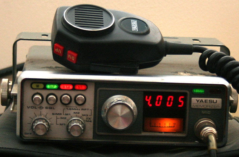 IBM PC. This was also in the days when most scanners had to be
programmed with front panel switches.
IBM PC. This was also in the days when most scanners had to be
programmed with front panel switches.
The Memorizer nomenclature was due to the fact that the series of radios was capable of saving a preferred channel or split into memory. Today even the simplest radio can save dozens, if not hundreds, of frequencies in memory. Back in the late seventies, being able to hold even one stored frequency (as the original 2 meter model could do) was a big deal and a major operating convenience. Through a combination of memory button, and switch, a total of two simplex, three standard offset, and one manual offset channels could be memorized. So technically, there were six memories.
Other cutting edge features of
the day were the PLL synthesized frequencies, digital read out, ability
to scan the band, and
built in tone burst - with optional tone squelch. Wow!
This particular radio covers the
remaining portions of the 220 band, going from 222 MHz to 225 MHz, using
600 channels with a 5 KHz spacing. Duplex operation is possible using a
standard 1.6 MHz split, or a slightly more difficult manually adjusted split. Early
versions radiated 10 watts, though latter models are said to have put out 25
watts. Operation is simple, without the various menus and submenus that seem so prevalent on most
of today's radios. It is an FM only radio.
This is a great looking radio, and
built like a tank. It is somewhat heavy, at six pounds, and somewhat large for a
mobile, though it makes for a nice compact base unit. In a purely subjective
sense, the radio has a nice feel to it, and strikes the operator as a radio,
rather than a bit of computer gear. Power requirements are
 for
the usual 13.8 volts, with a draw of 0.5 amps on receive and 2.5 amps on
transmit. The included microphone has buttons to adjust frequency up and down.
for
the usual 13.8 volts, with a draw of 0.5 amps on receive and 2.5 amps on
transmit. The included microphone has buttons to adjust frequency up and down.
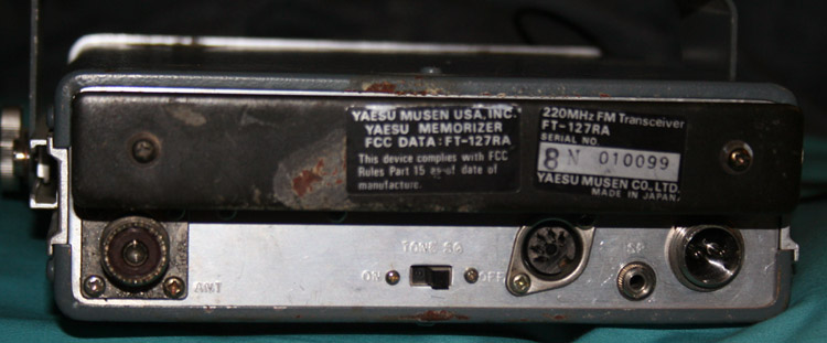
There is a rear panel connector for an accessory. Note that this is not for computer control. It is for an outboard tone generator. A dummy plug is included with the radio, and it must be kept plugged in at all times, or the radio will not work - no sound. If you have bought your radio used (very likely these days), and it is missing this plug, you can get the radio working by shorting pins one and four (See below).
The Rear panel also has an external speaker jack, the power connector, antenna connector, and the switch for activating the optional tone board. In addition, there is a pretty good sized heat sink sitting back there.
The ability to work 220 is kind of
exciting for me. Getting on a new band is sort of like getting a new toy, or
going on a vacation and visiting a new place. Adding to the adventure is the
fact that 220 is not a widely used band. On the other hand, it might be better
if the band had a few more users.
Adventures in 220 land - the 1.25 meter band
Sadly, the limited memory on this
radio may be enough for the 220 band, in most areas.
In most areas, if you are using the
1.25 meter band, you have it pretty much to yourself. Though this is usually
called the 220 band, 220 MHz is no longer part of the U.S. band plan. In the
Untied States, allowable frequencies for amateur use are from 222 MHz to
225 MHz. The FCC removed the 220 MHz to 222 MHz portion from the band
plan in the 80's to turn it over to commercial use (primarily at the
request of UPS, which then never followed through).
The band has been not so much abandoned as ignored, more out of confusion than malice. When looked at on its own merits, the 1.25 band would appear to be a nearly ideal band, in terms of operating characteristics. Being a VHF band, it does not exhibit the scatter and attenuation characteristics of UHF; but it has a short enough wave length that it allows for an efficient antenna that is short and practical - the best of both worlds.
Despite its
advantages, 1.25 meter never really caught on. The
loss of part of the band is only a part of the reason. Like any radio
band, 220 is a mixed bag. Its unique features are listed below.
The Bad
The band is not used in many countries.
There is a limited
assortment of gear available, and it is expensive.
There is
lots of activity on 2 meter and 440 - many operators see no need to get
involved with another band.
For a time there was some confusion
regarding frequency spacing, with different and non uniform channel and frequency widths.
The future of the band is somewhat uncertain, and there is some concern that it might be lost.
The Good
The band is private, because it is
not included on most scanners.
It has most of the characteristics of 2 meter, but uses antennas less than half the size. It does not scatter to the extent of 440.
If you get yourself a base or repeater, a mobile and a few handhelds, you can have a whole band to yourself in many areas.
In my own personal case, I
bought this radio, because it was relatively inexpensive (about $70), and could
cover the whole band. I spent as much money on the commercial radio I use for
FRS/GMRS - even my CB radio cost more. The reason for the frugality is that I do
not wish to invest heavily in a band with so little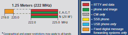 use, and a possibly limited
future. Even six meter FM seems busy compared to 220.
Still, I wanted to give 220 a try, and wanted a transceiver that could
cover the entire band. I also wanted a digital display, and the ability to
access repeaters.
use, and a possibly limited
future. Even six meter FM seems busy compared to 220.
Still, I wanted to give 220 a try, and wanted a transceiver that could
cover the entire band. I also wanted a digital display, and the ability to
access repeaters.
Most operations will be FM via repeater - if you can find one. There are four repeaters in my metro area, out of which I can only hit one on a regular basis. many areas have little or no activity and few if any repeaters. The standard offset on 220 is 1.6 MHz A fairly large proportion of the repeaters on this band do not require a tone. Though I have heard such radios exist, I am aware of no operations on AM or SSB. The band is also somewhat unique, particularly for a VHF band, in having a gap, between its upper and lower limits.
The band has been around since the thirties, and is quite ancient for a VHF band. Up until the sixties, it and the rest of the VHF/UHF bands were largely limited to commercial or experimental use. Though the antennas for these bands are relatively small, the electronics, shielding, and connection of the higher frequencies is quite complex, when compared to the regular HF bands.
Solid state electronics allowed for a bit of a boom in VHF/UHF. Permitting these radios to be made small enough and cheap enough to be practical for the more casual user. It also permitted repeaters to be more easily and more inexpensively set up. Large numbers of commercial, public service, and military radios were made at or near the 440 and 2 meter bands, permitting a great economy of scale to be passed onto the ham radio community. The same was not true of 220. The 220 band is sandwiched between Television channel 13, and the military aviation band. Neither use large numbers of radios, and neither are practical sources for surplus gear.
Future possibilities
Interestingly, the loss of part of the band may ultimately save it, and increase its popularity. One big reason for the slow start that 220 has gotten, is the dearth of applicable radios. For most of its history, the adjacent frequencies were used by the military, and by commercial television. Where the more popular 440 and 2 meter bands had nearby police, commercial, and business users, there was no such common use on 220. This may soon change.
With the loss of
the 220 MHz to 222 MHz portion of the band, and its reassignment to commercial
and maritime users, we may see some relatively large scale production of radios
for commercial use. This might filter down to amateur operators in a larger a
larger selection of radios, and lower prices. It will result in a large number
of radios produced for commercial users, many of which will eventually filter
down to amateur operators.
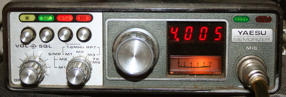
Operation
 Operation of the radio is simple and
basic. In many ways it operates like an overgrown handheld. An old fashioned red
LED indicates frequency, which is adjusted with a large rotary dial in the
center of the front face. The rotary
dial uses an optical electrical system, rather than an older style set of
switches - cutting edge stuff for the day. The dial scrolls through the band in
10 KHz steps. A pushbutton towards the left hand side of the front panel
increases frequency by 5 KHz, and lights an indicator lamp when depressed.
Frequency is indicated by a four digit red LED, with the 5 KHz indicator lamp
showing the last digit. Below the frequency display is an illuminated S/RF
meter.
Operation of the radio is simple and
basic. In many ways it operates like an overgrown handheld. An old fashioned red
LED indicates frequency, which is adjusted with a large rotary dial in the
center of the front face. The rotary
dial uses an optical electrical system, rather than an older style set of
switches - cutting edge stuff for the day. The dial scrolls through the band in
10 KHz steps. A pushbutton towards the left hand side of the front panel
increases frequency by 5 KHz, and lights an indicator lamp when depressed.
Frequency is indicated by a four digit red LED, with the 5 KHz indicator lamp
showing the last digit. Below the frequency display is an illuminated S/RF
meter.
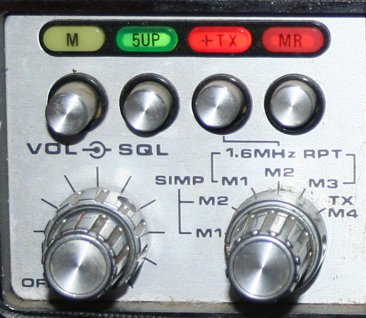
To the left of the front panel are the volume and squelch knobs, as well as the mode selection knob. Above the knobs is a row of four buttons, with indicator lights. These are used to set repeater functions, and to toggle the frequency an extra 5 KHz. The volume and squelch controls work in the usual manner; but the mode selection knob takes a bit of explaining. This, and much of the rest of the eccentric operating style of the unit are due to the novelty of repeater operation at the time of its design. They are also due to the expense of digital circuitry in those days. Analog electronics, and mechanical switches were cheaper, more familiar, and easier to design.
The mode selection knob is what you use to select your memory location, and your type of operation. It has six selections - one for each memory location. The first two selections, Simp M1 and M2, are for simplex operation. The next three, 1.6 MHz rpt M1, M2, and M3, are for operation with a standard separation of -1.6 MHz.. The final selection, TXM4 is for use with a user selected separation. The switch settings serve to select the memory to use, with the memory button saving the setting.
The MR button to the right of the row of buttons, is the key to operation. In today's terms, this button switches between VFO operation, and channelized operation. With the MR button out, the Mode selection does not matter. The radio selects frequency by use of the frequency dial. With either of the simplex selections, transmission mode is simplex. With any of the other selections, operation is uses a -1.6 MHz split. This split can be changed to a +1.6 MHz, by use of the +TX button. Depressing the M (memory) button, to the left of the row, will save the current memory to the current channel.
Depressing the MR (memory recall) button,
to the right of the row, channelizes operation. With the button down, changing
the position of the mode selection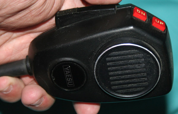 knob will select whatever frequency was saved in the memory for that particular
channel. Again, the first two selections are simplex, the next three are duplex
with the standard 1.6 MHz shift, and the last is adjustable to any split. With
the MR button down, the FT-127 RA acts like a six channel radio. As archaic as
the system seems, to those of us used to the digitized radios of today, it does
allow for easy switching between channels and scanning operation. There is no
battery back up, so when power is lost, the memories all clear.
knob will select whatever frequency was saved in the memory for that particular
channel. Again, the first two selections are simplex, the next three are duplex
with the standard 1.6 MHz shift, and the last is adjustable to any split. With
the MR button down, the FT-127 RA acts like a six channel radio. As archaic as
the system seems, to those of us used to the digitized radios of today, it does
allow for easy switching between channels and scanning operation. There is no
battery back up, so when power is lost, the memories all clear.
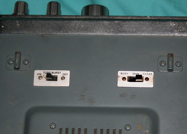
The radio has a scan feature, which permits monitoring the whole band. This is done through the Up/DN buttons on the microphone. The feature is turned on by a switch on the bottom of the radio. It can be set to scan for clear channels or busy channels. There is also a manual setting, which essentially turns the feature off, allowing the UP/DN buttons on the microphone to manually shift the frequencies.
The radio has a tone burst feature, to open old style repeaters. The switch for this is on the bottom of the radio, and will probably not be used often, these days. Switching the tone burst on causes a brief 1800 Hz tone to sound when the microphone keys up. Back in the old days, this is how you opened a repeater. Note that the tone burst only sounds for a fraction of a second, and is not continuous tone. I am unaware of any repeaters that still use this system; but you never know.
For modern repeater systems, CTCSS operation is possible with an optional tone
board; but this can be a problem. Amateur repeaters were not common,
 when
this radio was produced. In those mostly pre-digital days, repeater operation
was still exotic, and repeater gear was still expensive. The tone board option
was quite rare. Finding one today is difficult and expensive. Even so, it is
worth the effort on 220, because 220 gear is generally so costly. Modern
versions of the old tone boards are made by Comspec (www.com-spec.com ), and can
be installed in place of the originals.
when
this radio was produced. In those mostly pre-digital days, repeater operation
was still exotic, and repeater gear was still expensive. The tone board option
was quite rare. Finding one today is difficult and expensive. Even so, it is
worth the effort on 220, because 220 gear is generally so costly. Modern
versions of the old tone boards are made by Comspec (www.com-spec.com ), and can
be installed in place of the originals.
Even with a tone board installed, tone operation can be a bit strange. CTCSS tome operation is switched on and off through a slide switch on the back of the radio. Even more inconvenient is the method of selecting tones. There is no front panel control for tone selection, they are selected by setting dip switches on the board itself, while it is in the radio. The only way to select a different tone, is to open the top cover of the radio, and change the position of the dip switches. Fortunately for me, a majority of the few repeaters in my area use the same tone (127.3). Setting tones via dip switch also means that you can not set a tone without having the manual to tell you what the switch setting must be for a given tone.
In addition to this, when tone operation is selected, the radio expects incoming signals to contain a tone, and will not recognize any that do not. While incoming tone squelch can be handy, not all repeaters transmit a tone. It would be nice if this could be turned off. Probably the best way to operate this unit, for repeater use, is with an outboard tone generator. Comspec makes these as well, and the radio is designed to accept such a unit.
Internally, the radio is
open, easy to work on, and holds no hidden wires, or other traps to snare the
unwary. Five screws get the top off, five more remove the bottom. The forward left hand portion of the top PC board has a large blank
spot, intended for the optional tone board. There are nine post pins over which
the board is mounted. In addition to being mounting points for the board, these
pins are also connections to the circuit board.
the bottom. The forward left hand portion of the top PC board has a large blank
spot, intended for the optional tone board. There are nine post pins over which
the board is mounted. In addition to being mounting points for the board, these
pins are also connections to the circuit board.
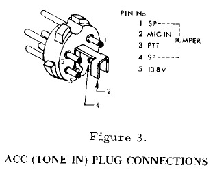
**A number of radio enthusiasts have built their own tone boards, and a PL encoder board is not such a difficult project. They can easily be built for $10 - $15, or a factory built unit from Conspec can be purchased for about twice that. I have included a pin out diagram below, for those who wish to construct or modify their own internal tone boards.**
The manual includes instructions for internal alignment, and set up, which can be very handy with an older radio. these instructions, the easy access to components, and the general build quality ensure that these already thirty year old radios will probably be around for a long time.
One overlooked factor, and something which is very important for the buyer of used radios, is the accessory connection on the back of the radio. This was designed to permit use of an external tone generator. the connector has pins for power, ground, PTT, mic in, and a speaker pass through. The pass through actually interrupts the speaker circuit, and would disable the speaker, if it was not shorted. When an external encoder/decoder is installed, it would complete the circuit. Without such a device, it is necessary to have a dummy plug in place, which shorts pins 1 and 4, to complete the speaker circuit. Without this dummy plug, the radio would power up, and everything would work - you could even transmit; but there would be no sound.
 If your radio is missing the dummy plug, as mine was, you can wire up another,
or you can simply run a
If your radio is missing the dummy plug, as mine was, you can wire up another,
or you can simply run a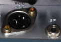 jumper across pins one and four. Despite their numbers,
these pins are adjacent. A bit of copper wire, or a bent connector pin, and the
job will be done. I often wonder how many of these radios are sold cheaply,
because they are thought to be broken due to the missing dummy plug. Needless to
say, this modification should be done with the radio off and the power
disconnected. Please note that pin five carries the full 13.8 volts, and that
the radio chassis is set as ground. I was lucky enough to blow a fuse, rather
than destroying my radio, by attempting to find the correct orientation of the
jumper, while listening for white noise from the speaker. Also make certain of
the orientation of the socket itself. These appear to have been installed
"upside down", in relation to the diagram in the manual.
jumper across pins one and four. Despite their numbers,
these pins are adjacent. A bit of copper wire, or a bent connector pin, and the
job will be done. I often wonder how many of these radios are sold cheaply,
because they are thought to be broken due to the missing dummy plug. Needless to
say, this modification should be done with the radio off and the power
disconnected. Please note that pin five carries the full 13.8 volts, and that
the radio chassis is set as ground. I was lucky enough to blow a fuse, rather
than destroying my radio, by attempting to find the correct orientation of the
jumper, while listening for white noise from the speaker. Also make certain of
the orientation of the socket itself. These appear to have been installed
"upside down", in relation to the diagram in the manual.
This connection does give me the option to add an outboard CTCS unit, if I suddenly decide it is too much trouble or expense to build an internal unit. This would also give me the option of using the outboard unit on other radios, that might also be missing an internal PL unit.
This section is not yet complete; but will
be updated after I complete installation of my tone board. A number of radio
enthusiasts have built their own tone boards, and a PL encoder board is not such
a difficult project. They can easily be built for $10 - $15, or a factory built
unit from Conspec can be purchased for about twice that. I have included a pin
out diagram below, for those who wish to construct or modify their own internal
tone boards. In my case, I just bought one. While it's fun to build your own, I
like things to work the first time, and am no engineer.
 For
those who like to build their own, I have included a link below to a site with
instructions for an easy to build unit. I have also included a link to Comspec,
where you can buy a factory built unit. Times have changed. At one time tone
capability was a luxury, an optional extra, and a cutting edge feature. These
days it is a necessity. No one would consider selling a VHF or UHF radio without
the feature. It has also become quite a bit less expensive to impliment.
For
those who like to build their own, I have included a link below to a site with
instructions for an easy to build unit. I have also included a link to Comspec,
where you can buy a factory built unit. Times have changed. At one time tone
capability was a luxury, an optional extra, and a cutting edge feature. These
days it is a necessity. No one would consider selling a VHF or UHF radio without
the feature. It has also become quite a bit less expensive to impliment.
Modern units use computer generated tones, while the older units used (and continue to use)dedicated chips. The dedicated chip means that tone selection is made by making adjustments to the board itself - in this case by means of dip switches. Direct tone selection through the radio is not possible, and was not on any radios from this era. This would come latter with the new computer controlled and enhanced radios introduced in the eighties. To change tones, the case will need to be opened. As there were fewer repeaters back then, and many did not require tones, this was not much of an issue. Even today, there are few repeaters on the 220 band. In my own area, all of my local repeaters use the same tones. While it would be simple enough to cut a hole in the case, over the mounting position of the board, this would be sloppy, and would compromise the integrity of the unit. it is also more trouble that I really want to take.
The diagram of pin outs can be
superimposed upon the photo above, to aid in wiring. Whether
you
build or buy, you will need the pin outs for proper connection. Set up is easy,
with the most difficult part being the mounting of the board. I used double
sided tape, and put it in the same spot that was meant for the original. I
bought a comspec board for about $30, which holds a single chip, and the
components needed to drive it. The unit generates a selection of 64 tones, and
has a selectable reverse burst feature, and selectable timing. It is designed
for internal installation.
I had considered an outboard tone generator, that might be amenable for use in multiple radios; but I like the neatness of internal boards, and have no other radios that might need addition of tones. For those who prefer, there is a rear connector for use with an outboard tone unit. The outboard unit also offers only 32 tones, rather than the 64 of the internal unit.
The tone board is activated through a slide switch on the back of the radio. Not very convenient; but having the capability at all was a pretty big deal back when this radio was produced. The board kicks in on transmit, and allows me to hit the few repeaters available in the area. In some cases a mod may be required, in order to permit listening to non-tone generating repeaters. Few repeaters work this way these days; but most modern radios have the capability to do this.
With another $30 invested for the tone board, added to the $70 paid for the radio, the whole thing came in at around $100. For this, I have a well built, 1.25 meter radio that can access modern repeaters, is programmable in a quant sort of a way, and puts out around 10 watts. With the addition of tones, this radio is now everything I could want from a radio to get me into the 1.25 meter band.
Antenna System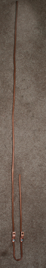
Experiences with my 440, GMRS, and 2
meter systems convinced me to make a groundless vertical antenna for my 220 system. To my
mind, this is the best general use, omnidirectional antenna you can have, for
VHF, UHF, and above. This is particularly true for FM repeater use, since this
is almost universally vertically polarized. It is also easy and inexpensive to make. As I still had
some soft copper tubing left from my 2 meter and six meter projects, materials
would essentially be free. As this unit is to be used entirely in FM mode, there
is not need for a horizontal antenna. I can't imagine working skip on such a
high frequency, even were this to be a multi mode unit. Had I not already had
the materials on hand, construction would have still been under $10. Small cheap
and easy to make, yet everyone knows that the antenna is the most important part
of the radio system.
The antenna is small and light enough that it hangs from the wall of my second floor shack. It is connected by a very short length of coax, to keep losses low. This is my only 220 antenna. No other is really required, as virtually all transmission (what little there is) on 220 is vertically polarized FM mode. Even so, I am considering a beam, since at such a frequency a beam would be comparatively small.
Instructions for making this antenna are at a link in my link sections. My own step by step procedure is on a one of my antenna pages. I recommend the soft tubing, as it requires no brazing or soldering. Mounting is easy. The finished antenna has no ground elements, and so once built it is narrow enough to simply hang on a wall.
This unit is mounted high on the wall of my second floor shack, which puts it about twenty five feet above the ground. This should give me a good 20 miles line of sight to another base, and around half that to a mobile. VHF, particularly the upper portion, is not exactly shortwave, so skip is not really a factor here. Antenna height is critical, far more so than on HF. The dearth of 220 activity around here makes range that much more important. Unlike the far more popular 2 meter band, there are no thousand watt repeaters on 500 foot towers.
The phone and data portions of the 220 band are only 3 MHz wide, or a bit over 1% of the frequency. Even including the separate forwarding frequency at around 219 MHz, you are still only talking 6 MHz, or about 2% of the frequency. What this means is no tuner and pretty good SWR across the whole band from a single antenna, once proper tuning is done. The antenna is fed from a six foot length of coax, helping to keep any feedline losses low.
We are also getting pretty close to UHF frequencies here. This means that the quarter inch OD of this tubing is a significant percentage of the wavelength. This gives very wide bandwidth, and also allows for a somewhat shorter antenna than standard calculations would suggest. The tubing, and connectors are of solid copper, except for the SO239 which is silver plated. Factory antennas are usually made from aluminum or stainless steel. Copper conducts electricity roughly 60% better than aluminum, and many times better than stainless steel. This should reduce losses through heating and resistance, and thus make the antenna somewhat more efficient.
Antennas are one of the few things that the amateur operator can still make, that are worth the effort. At one time, we built all our own gear, including the transmitters, amplifiers, and power supplies. As radio gear got more complicated, and more capable, it became the province of engineers, design teams, and high tech manufacturing facilities. The last gasp for the home builders was the selection of kits offered by the old Heath company. Even these were discontinued, sometime in the eighties, and were never truly homebrew.
A homebuilt radio today, would take time, effort, and probably cost more than a far better radio built in a factory. Antennas are different. The home builder can make a unit of the best materials, and customize it to his surroundings, and type of operation. There is no factory that makes a 220 antenna, at any price, which can match such an antenna. Such things do not lend themselves to mass production. There are a few custom antenna builders out there who make units; but these are expensive, sometimes backordered, and not always of consistent quality. Even here, most are made of aluminum.
I may tinker with this antenna a bit, and might even decide to convert it to a Slim Jim someday, which is not too difficult to do. In the meantime, it is plenty good enough to hit the few repeaters we have around here.
Specifications
Links
Along with some links for the related FT-227 radio
| Eham Review | J-Pole Antenna | 1.25 Explained | FT-227 |
| Home brew tone | 9600 Baud Mod | 227/127 resources | Comspec PL board |
219-220 Digital
222-222.05 CW
222-222.05 Moonbounce
222.05-222.06 Beacons
222.1-222.25 Weak signal, rag chew
222.1 National Calling Frequency
222.25-223.38 Repeater inputs
223.4-223.52 FM Simplex
223.54 FM Calling Frequency
223.52-223.64 Digital
223.64-223.70 Links control
223.71-223.85 FM simplex, Digital
223.85-224.98 Repeater outputs