MFJ-249
| MFJ -99 and MFJ-66 |
An antenna analyzer is an almost magical piece of gear to many radio
enthusiasts. It is a simple device, in its own way. It consist of a
variable oscillator,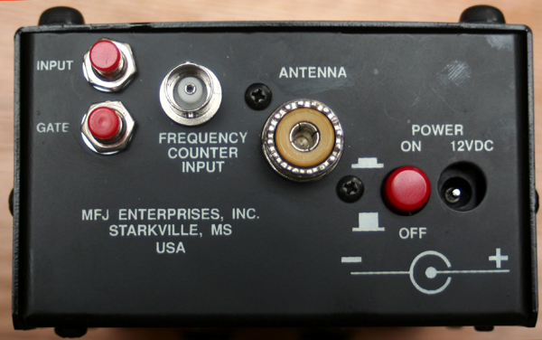 a frequency counter, and an RF bridge/unbalance indicator (also known as an SWR
bridge). This combination of circuits lets you get a pretty good idea of what
you antenna system, is doing and how it is performing.
a frequency counter, and an RF bridge/unbalance indicator (also known as an SWR
bridge). This combination of circuits lets you get a pretty good idea of what
you antenna system, is doing and how it is performing.
This particular unit is an MFJ-249. It is an older model and is long out of production. The newer model, listed as MFJ-249b, has dispensed with the analog SWR meter, and integrated this function into the LCD. The unit covers frequencies from 1.8 MHz up to 170 MHz - basically 160 meters to 2 meters. It can also be used for CB.
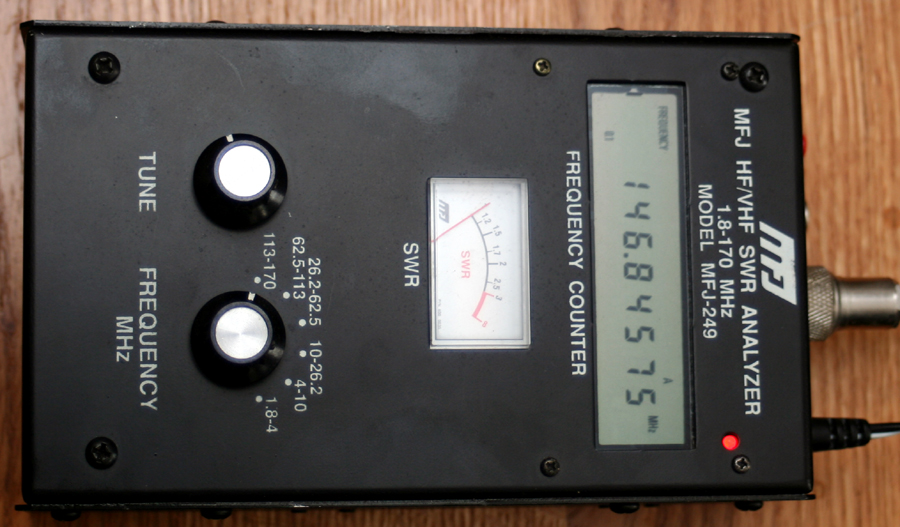
Controls are simple enough, and the unit is easy to use. The front panel has a selector and a tune dial for the oscillator. It also has the LCD display of the frequency. The top of the unit has connectors for power, the antenna under test, and an external antenna to be used for the frequency counter. It also has the power switch, a switch to select between the antenna inputs (A for the SO-239, and B for the BNC), and the gate button to adjust frequency averaging. Please note the polarity indicator for the power supply. There is no protection circuit. If you plug in a supply with the incorrect polarity, you will fry the components.
The simplest and most common task for this unit is to determine antenna resonance. This is done by connecting the unit to the antenna under test, selecting the proper range for the oscillator, and then swinging the SWR needle with the tune dial until the lowest SWR is shown. The frequency is then read from the LCD. This is handy and quick. Now there are many other ways to do the same thing. A noise bridge, an SWR meter, and a dip meter will all accomplish the same thing; but an antenna analyzer does it fast, accurately, and without the need to transmit (in all fairness, a dip meter does not require the radio to be powered up either). Additionally, an SWR meter will give the SWR; but a high SWR can be caused by an antenna that is too long, too short, or by something else in the antenna system. The SWR meter does not indicate the cause of the problem. An analyzer, by giving the resonant frequency, will tell you what is wrong.
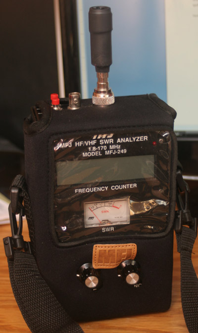
The first thing I did after taking the unit out of the box and checking it over, was to check the resonance of my homebuilt 2 meter Slim Jim antenna. I built this antenna a couple years ago out of copper tubing, and tuned it using a standard SWR meter. It has served me well; but you can't help wondering sometimes just how well it is tuned. I had initially tuned it using an unoccupied frequency right around 144 MHz - the center of the band. The photo at the top of the page shows the meter indicating the true resonance of my antenna - 146.84575. I was off a couple of MHz, in my initial tuning with the SWR meter; but all across the band, the SWR was under 2.
One of the great things about an analyzer is that you can scroll up and down the band in order to determine antenna band width. The oscillator does put out a small amount of RF, and if you listen on an HT while adjusting an antenna, you can hear the analyzer signal. It sounds a bit like a diesel engine idling, and can only be heard if the HT is within a few feet of the antenna under test.
There are a few things to mention about this tester. The first is that the oscillator is not particularly stable. You will notice it swinging, usually upwards, as you test. You can keep it relatively where you want it, by tweaking the tuning dial. MFJ advises that oscillator drift is normal and acceptable. This may be true; but I found it a bit unnerving to see the last two or three digits of the frequency readout changing constantly. In defense of MFJ, the Comet does the same thing, as do many other analyzers.
I also found that I got the best and most stable readings when I was not touching the case of the analyzer. Everything in the box is grounded to the case, including both antenna connectors. This may be why soft cases are such a popular option for these units; they keep user and analyzer insulated from each other. Additionally, when measuring low impedance antennas, the units become less accurate.
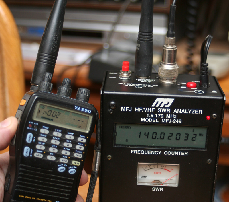
The next most popular use for this meter, after antenna tuning, is as a field strength meter, and a frequency counter. This is done by connecting the BNC connector (connector B) to a rubber duck or similar antenna. With this done, depress the red input button until you see the A indicator on the upper right of the LCD change to B. The readout on the LCD should immediately revert to zero. You will need to bring the antenna on the MFJ-249 within almost touching distance of the antenna of the source to be measured.
With the antennas of the analyzer and the transmitter under test nearly touching, keying up the transmitter should produce a reading on the MFJ LCD display. You will also note that the SWR indicator needle moves. With this set up, the SWR meter acts as a field strength meter. MFJ advises that sensitivity is from 500Mv, to a maximum of 5 v. The 5 v maximum should never be exceeded; doing so may damage the unit.
The manual gives the procedures for measuring many other things, such as velocity factor, loss, impedance, capacitance, and inductance. All of these things require a bit of ingenuity, and also some special connections through probes or home brewed circuits. Newer models have these circuits already built in.
MFJ does sell a kit (MFJ-66) consisting of coils which connect and turn the unit into a dip meter. No, a dip meter doesn't measure the level of inanity in your fellow hams. A dip meter indicates the resonance of a circuit. For those who are unfamiliar, a dip meter creates an RF field of a certain frequency around a coil. When this coil is brought into close proximity with a tuned circuit, the frequency of the field is adjusted unit a dip is read in the meter. This dip indicates that some of the energy has left the field and been absorbed by the circuit under test. This occurs at the resonant frequency of the circuit under test.
 The manual for this unit has some pretty in depth instructions about how to
build various probes to test for an assortment of properties. As an additional
add on, you can purchase a kit that will allow you to use this analyzer as a dip
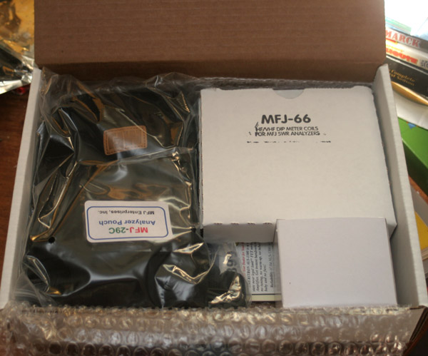
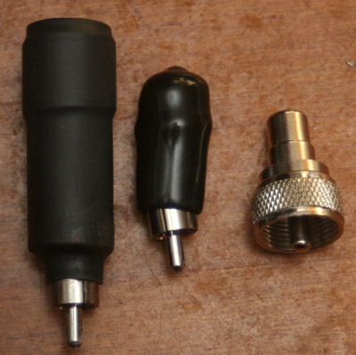
meter. The MFJ-66 kit comes with a pair of coils that look like little antennas,
and an adapter that allows you to mount them on the antenna connector. The
MFJ-99 includes the coils, as well as an AC adapter and a soft case (which
didn't quite fit my unit).
The manual for this unit has some pretty in depth instructions about how to
build various probes to test for an assortment of properties. As an additional
add on, you can purchase a kit that will allow you to use this analyzer as a dip
meter. The MFJ-66 kit comes with a pair of coils that look like little antennas,
and an adapter that allows you to mount them on the antenna connector. The
MFJ-99 includes the coils, as well as an AC adapter and a soft case (which
didn't quite fit my unit).
This seemed like a natural enough addition, and though there is a lot of overlap, there are times when a dip meter can be a very useful tool and do things that an analyzer can not. Basically, an antenna is a very special kind of resonant circuit.
While an analyzer measures SWR, by reading signal return when connected to an antenna, a dip meter actually measures energy loss. What happens is that a resonant circuit will absorb some energy at its resonant frequency. A dip meter will put out an RF field, and as you adjust the frequency up and down, you watch the meter until it dips - showing that power has been absorbed from the RF field. So in a sense, a dip meter measures just the opposite of what an analyzer measures.
One of the great things about a dip meter is that it can measure any kind of resonant circuit - coils, antennas, baluns, tanks - you name it. It can do this without having to be directly connected. You simply put the dip meter coil in proximately of the circuit under test, and adjust the frequency until the circuit couples and absorbs energy from the dip meter. This registers as a dip in power on the meter
Performance of the unit as a dip meter is
marginal. Still, it
 does
have some utility, and can be a handy thing to have around. The main limitation
is in the range at which the unit is sensitive. What playing around with this
thing has really done for me is make me want to get myself a real dip meter,
with a full set of coils. I have read a number of complaints about the poor
performance, yet it is a usable enough feature as long as you don't expect too
much. Recall that this is a set of two coils that attaches to an analyzer. the
cost of the kit is $25 - $35. A dedicated dip meter will cost well over a
hundred dollars and contain an entire set of coils.
does
have some utility, and can be a handy thing to have around. The main limitation
is in the range at which the unit is sensitive. What playing around with this
thing has really done for me is make me want to get myself a real dip meter,
with a full set of coils. I have read a number of complaints about the poor
performance, yet it is a usable enough feature as long as you don't expect too
much. Recall that this is a set of two coils that attaches to an analyzer. the
cost of the kit is $25 - $35. A dedicated dip meter will cost well over a
hundred dollars and contain an entire set of coils.
Within their limitations, the coils are good enough. Part of that limitation is that this unit will only work within the 1.8 MHz - 170 MHz range of the analyzer itself. It is somewhat insensitive, and you will have to watch very closely, since two coils are doing the job of a whole set of coils. The coils set is shown in the photo to the right, and yes one of the coils is crooked - typical MFJ. Yet, the coils work fine, crooked or not.
The larger coil has a range of 1.8 MHz through 50 MHz; but has good sensitivity only form 10 MHz to 20 MHz, with a drop off towards the ends of the range. The small coil is rated for a range of 20 MHz though 175 MHz, though it is only at its best between 100 MHz and 150 MHz. The coil kit by itself is called the MFJ-66.
A set of five coils would probably be better, and cover the range with more sensitivity; but such a set would also cost quite a bit more. MFJ customers are not known for their free spending habits. As I mentioned, the kit is good enough for casual use, inexpensive, and is a handy item to have around for spot checks. If you need precision, you are better off with a dedicated dip meter.
Also included in the MFJ-99 kit is an AC
adapter, of no particular note. It is a standard 12 volt unit that puts out a
half an amp, and has a positive center. The
 unit is designed for this
analyzer and the two function together as they should. A good adapter is a
requirement, since there is no protection circuit in the analyzer itself, and
the battery holders are not known for their durablity.
unit is designed for this
analyzer and the two function together as they should. A good adapter is a
requirement, since there is no protection circuit in the analyzer itself, and
the battery holders are not known for their durablity.
The final item in the MFJ-99 kit is a soft case. The case is made from the same kind of neoprene that is used in wet suits. So it should offer good protection. the most important thing the case does is isolate the user from the analyzer. I have noticed that my readings can change when I remove my hands from the unit.
The case has a plastic window for the meters, and cut outs for the various controls and inputs. Mine did not match exactly, but a bit of judicious work with a scissors put things right. The case includes a shoulder strap, and has a small Velcro compartment on the back which is perfect for storing the coils of the MFJ-66 kit.
Shown in the photo to the left is the MFJ-249 in all its glory, safely sequestered in its case, and set up as a dip meter for the 1.8 MHz - 50 MHz (10 MHz - 20 MHz nominal) range. All in all I am happy with the kit, and though use as a dip meter is limited, I do not feel my money was wasted. The MFJ-99 kit was around $50, which included the case, AC adapter, and dip coils. The accessories make an already versatile unit that much more versatile. The only thing I am missing is a field strength meter, and with a proper antenna and a bit of imagination, this unit will perform that function as well.
I may experiment with winding a few other coils for the unit. Now that I have the adapter, there is no real reason why regular dip coils may not be used as well. In addition, I am encouraged to try building some of the probes and circuits suggested in the manual to increase the functionality of the analyzer. The combination of variable oscillator, frequency counter and SWR bridge (really an RF detector), offer a number of possibilities outside of simply testing antennas.
For those who are interested in gadgets, spy movies, and the old James Bond culture, with a proper antenna you can use this unit to sweep for listening devices (bugs).
MFJ has garnered itself a reputation which is, to say the least, not to be
envied. "Mighty Fine Junk" is a typical appellation used by derisive or
disappointed radio amateurs. Yet one can't help but notice that MFJ pretty much
dominates the market for antenna analyzers. A lot of this is due to the
relatively low cost of the units. The Comet analyzer that I originally wanted
costs $425. The MFJ with similar capacities is around $270. The used unit I
ended up with cost just over $100, including shipping. Nothing else comes close
to matching this price. There are some much better units out there, from
companies like AEA, Autek, and Rigexpert, costing four and five times as much.
 The
pocket book is a powerful motivator.
The
pocket book is a powerful motivator.
The reason that MFJ, with its clear price advantage, has any competitors at all is due to what might charitably be called a relaxed attitude towards quality control. Much of the gear looks like Martin Jewett (the owner of MFJ), and his kids put it together after school, as a sort of a family project. The gear is also housed in what look like the kind of little metal project boxes a hobbyist might get for his homebrew projects.
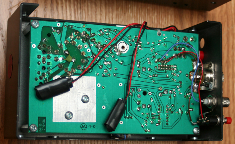
People who know MFJ, and are customers anyway, tend to immediately disassemble their units and check them for poor solder joints, missing parts, loose parts, and broken or bent assemblies. The loose, cracked, or cold solder joints tend to be the most frustrating, since they can cause intermittent problems. They also tend to be the easiest to fix, with a simple touch up from a hot soldering iron being sufficient.
A close look at the photo above shows a board that has been touched up a few
times. The upper left side, in particular, appears to have been gone over more
than once. You might also notice that the coax connector has been soldered
directly to the circuit board, and can easily have the solder joint broken by
normal use - a typical complaint for these units. Again, this is an easy fix. So
build quality was not great; but was better than some of the rumors and horror
stories had led me to expect.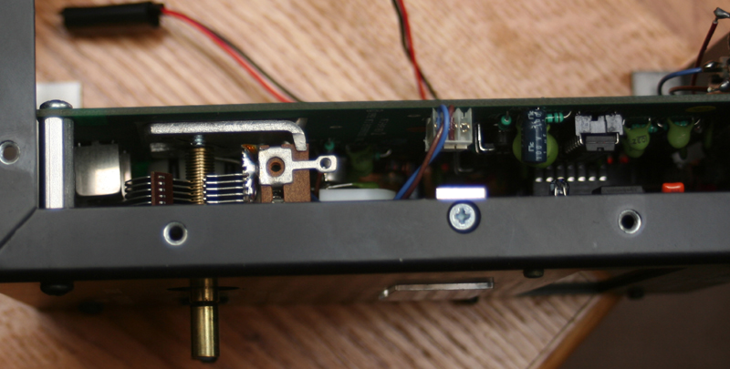
A recurring complaint with his unit is the cheapo battery holders. A pair of plastic battery holders houses four batteries each. The holders constantly break or come loose. The unit then needs to be disassembled (by removing eight screws and separating the two halves of the case), to put things right. Adding to the problem is that the battery holders connect with what look like standard nine volt battery connectors. Attempting to connect nine volt batteries to these connectors will fry the unit. In my own case, I either use an AC adapter, or an external 12 volt pack.
One other recurring issue, is that these units are affected by strong local signals. If you are getting erratic or illogical readings, this is something to check. You can test for this by switching to the B connector and seeing if there are any interfering signals. MFJ makes a filter for strong local RF.
All in all, I can't complain. I was aware of the serious criticisms of MFJ, before I bought the unit, so I made the purchase with my eyes open.. Once I got used to a few idiosyncrasies, I have had no issues, and have found the analyzer easy to use. I have also had quite a bit of fun with the frequency counter, and use as a field strength meter. For the amount of money I paid for this thing, I can't believe all the uses to which it can be put. I would buy this unit again, and now that I have shed a few of my fears about MFJ, may consider upgrading to one of their more advanced models.
| eham review | |||