The Kenwood TK-350
FM UHF transceiver
| GMRS and frequencies | Accessories | Programming |
| Disassembly/mod | Specifications | Manual |
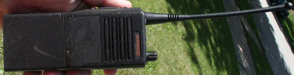
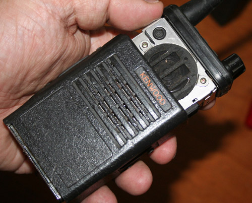
 This is an FM handy
talkie designed for commercial and government users. This particular version
uses the UHF bands, and is a type 1, which covers 450 - 470 MHz. While this is
not so good for the amateur 70 cm band, it is nearly ideal for use as a GMRS/FRS
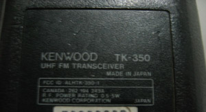
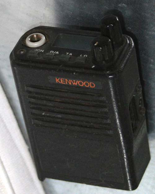
radio. The type can be determined by checking for the FCC type ID under the belt
clip, as shown in the photo to the left. This is essentially the same radio as the TK-250, but is a UHF version,
whereas the 250 is a VHF radio. These are great radios with a number of
accessories available, and are capable of displaying alpha characters.
This is an FM handy
talkie designed for commercial and government users. This particular version
uses the UHF bands, and is a type 1, which covers 450 - 470 MHz. While this is
not so good for the amateur 70 cm band, it is nearly ideal for use as a GMRS/FRS
radio. The type can be determined by checking for the FCC type ID under the belt
clip, as shown in the photo to the left. This is essentially the same radio as the TK-250, but is a UHF version,
whereas the 250 is a VHF radio. These are great radios with a number of
accessories available, and are capable of displaying alpha characters.
I presently have a number of these radios. As of this writing, I have three standard TK-350 radios, a pair of the TK-350G radios, and four of the related TK-353 radios. The G model is identical to the standard except that its ROM and programming allow for 160 channels instead of the 32 of the standard model. The TK-353 is essentially identical to the G model, though there are some differences - including trunking capability. The TK-353 also uses a different program (KPG-36D) to program the radio, though the same cable is used. I am working on a separate TK-353 page. Though these radios can be picked up at bargain prices, assume you will have to pay $30 - $60 for a working TK-350.
Even when older and outdated, commercial gear like this is quite a revelation for those of us used to consumer grade radios. Commercial radios are tough, they are well sealed against the elements, and they are designed for constant duty. They are also designed with much tighter specs, and tend to be much more stable than all but the best consumer grade radios. These radios can be dropped, banged, splashed, and have even been used as clubs by police officers.
These are twenty
year old radios, and have mostly led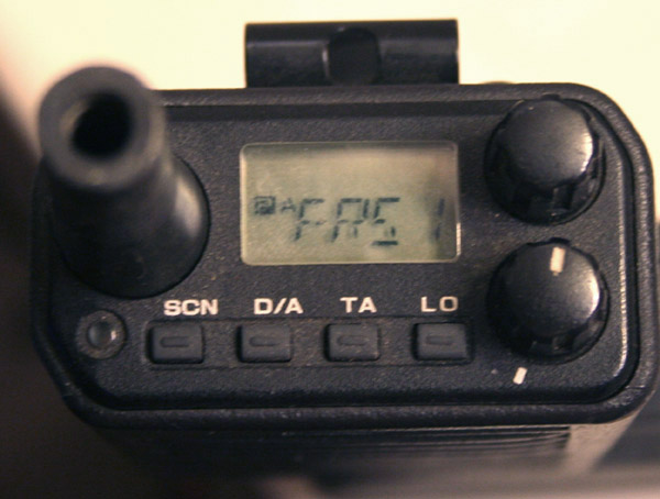 hard lives. Unless you are really
lucky, or pay through the nose, your radio will probably have some things wrong
with it, or be missing some items. The most common problem is a battery that
will not hold a charge, or perhaps no battery or no antenna is included. You may
also need to find a charger. None of these are particularly serious issues, as
long as the basic radio itself is in good condition. After market antennas can
be found for $5 - $6, and batteries can be had for about $20 - $25. Chargers run
about $25 - $30. Batteries for these radios were either the KNB-11A or KNB12A.
Both are still available. They are 7.2 volt 1200 - 1800 mah batteries. They use
a KSC14 charger - 9 volts at 1.5 amps.
hard lives. Unless you are really
lucky, or pay through the nose, your radio will probably have some things wrong
with it, or be missing some items. The most common problem is a battery that
will not hold a charge, or perhaps no battery or no antenna is included. You may
also need to find a charger. None of these are particularly serious issues, as
long as the basic radio itself is in good condition. After market antennas can
be found for $5 - $6, and batteries can be had for about $20 - $25. Chargers run
about $25 - $30. Batteries for these radios were either the KNB-11A or KNB12A.
Both are still available. They are 7.2 volt 1200 - 1800 mah batteries. They use
a KSC14 charger - 9 volts at 1.5 amps.
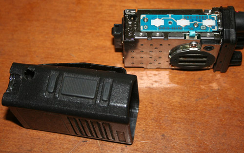
The actual radio portion of the unit is small. the modular construction allows for batteries, antennas, and microphones to be snapped in and out. Usually, the first thing a new owner does with one of these radios is get a new battery. The second is to get a new antenna. Other accessories are chargers, battery eliminators, tone pads, and programming cables. These radios put out a selectable 1, 2, or 4 watts on 32 channels (up to 160 channels on some models). They are capable of narrow or wide band operation.
The top panel contains the LCD display, as well as knobs for volume and channel selection. There is no squelch control. Squelch is adjusted when programming the radio. Small weatherproof function buttons are used for scan, power selection, adding and deleting scan channels, and enabling the talkaround feature. The repeater talkaround function is kind of neat, and is especially applicable on FRS/GMRS channels. What it does is reverse the duplex frequencies on duplex channels. This allows you to talk to other handheld units using repeater splits, without having to go through a repeater.
The top panel also has an LED, which lights red when transmitting, and green when the channel is busy. A programmable function will not allow you to transmit while the channel is busy, but this can be turned off (as I did on my radio) while programming. While the feature makes sense for commercial users on company frequencies, it is not such a good idea of GMRS/FRS frequencies where there is often a bit of interference. These radios are also capable of being configured for tone activated talk groups. This is another great feature for the commercial user, but not of much use to the average radio enthusiast.
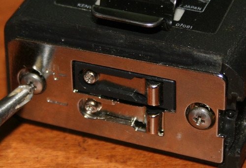
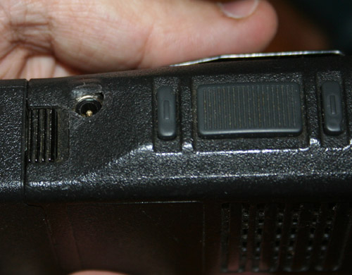
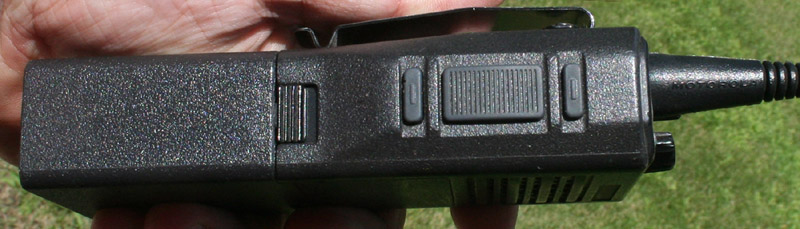 The side of the unit, under the antenna, has the PTT switch, as well as switches
for the display light, and monitoring over squelch. The monitor feature is
handy, because squelch can not be manually turned down. Also on this side of the
unit is the battery release. Pushing up on the release allows the battery to
slide out of the other side of the unit.
The side of the unit, under the antenna, has the PTT switch, as well as switches
for the display light, and monitoring over squelch. The monitor feature is
handy, because squelch can not be manually turned down. Also on this side of the
unit is the battery release. Pushing up on the release allows the battery to
slide out of the other side of the unit.
The side of the
radio opposite the antenna has connections for the microphone/speaker, and for
the programming cable. Included with the radio is a cap to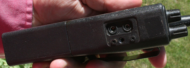 seal these connections from the elements, when these accessories are not being
used. The programming cable uses the same connection as the speaker/mike, and is
used with a standard PC RS-232C comm. port. These radios can be programmed in
the field, but it is much easier to set everything up on a PC and download it to
the unit's ROM. I have a section on radio programming below.
seal these connections from the elements, when these accessories are not being
used. The programming cable uses the same connection as the speaker/mike, and is
used with a standard PC RS-232C comm. port. These radios can be programmed in
the field, but it is much easier to set everything up on a PC and download it to
the unit's ROM. I have a section on radio programming below.
I use these radios on GMRS frequencies, though they were designed for business UHF. Many ham operators program them for 70 cm, but 32 channels (or even the 160 channels these units can use when maxed out), are not enough to even remotely cover 70 cm. As a GMRS/FRS transceiver, these radios are everything that we all hoped for as boys from our walkie talkies. A handheld like this can get a range of about five or six miles when talking to another handheld, and maybe another mile or two when talking to a mobile. When used with one of the few GMRS repeaters around, you can probably hit a repeater about 15 - 25 miles away.
While a full powered CB walkie talkie, putting out the same amount of power has a potential for greater range, such a unit only exploits this advantage with a suitable antenna. In the case of the walkie talkie you are talking about at least a four foot antenna. A full sized antenna for a GMRS/FRS unit is perhaps six inches long. This is far handier than trying to maneuver around with a long CB whip antenna. While many CB walkie talkies now have little rubber duck antennas, this drastically reduces their range, as such an antenna is very inefficient at CB frequencies. GMRS/FRS also has the advantage of being FM mode radio.
In order to use these radios on GMRS frequencies, you must have a GMRS license, at a cost of $85 for five years. It is also a requirement that a station call sign be given every ten minutes during transmission, or at every contact. Other family members can access the service on your license, and you are allowed up to 50 watts of power (7 watts on shared FRS/GMRS frequencies). Though most handhelds only put out the four or five watts of a CB walkie talkie, mobiles and bases, as well as repeaters can use the full fifty watts.
GMRS uses 23 frequencies, like the original CB, but the frequencies re divided up differently. There are seven simplex channels (Shared with FRS), and eight duplex channels for use with repeaters. Most GMRS radios also have the seven standard simplex FRS frequencies. GMRS licensees are allowed 50 watts on GMRS frequencies and GMRS/FRS shared frequencies, and 7 watts on FRS only frequencies. I have lots more information on GMRS/FRS on my GMRS/FRS page.
| Channel | freq | freq (duplex) | tone | name |
| 1 GMRS 550 | 462.550 MHz | 467.550 MHz | ||
| 2 GMRS 575 | 462.575 MHz | 467.575 MHz | ||
| 3 GMRS 600 | 462.600 MHz | 467.600 MHz | ||
| 4 GMRS 625 | 462.625 MHz | 467.625 MHz | ||
| 5 GMRS 650 | 462.650 MHz | 467.650 MHz | ||
| 6 GMRS 675 | 462.675 MHz | 467.675 MHz | ||
| 7 GMRS 700 | 462.700 MHz | 467.700 MHz | ||
| 8 GMRS 725 | 462.725 MHz | 467.725 MHz | ||
| 9 "5625" or "FRS 1" | 462.5625 MHz | |||
| 10 "5875" or "FRS 2" | 462.5875 MHz | |||
| 11 "6125" or "FRS 3" | 462.6125 MHz | |||
| 12 "6375" or "FRS 4" | 462.6375 MHz | |||
| 13 "6625" or "FRS 5" | 462.6625 MHz | |||
| 14 "6875" or "FRS 6" | 462.6875 MHz | |||
| 15 "7125" or "FRS 7" | 462.7125 MHz | |||
| 16 FRS 8 | 467.5625 | |||
| 17 FRS 9 | 467.5875 | |||
| 18 FRS 10 | 467.6125 | |||
| 19 FRS 11 | 467.6375 | |||
| 20 FRS 12 | 467.6625 | |||
| 21 FRS 13 | 467.6875 | |||
| 22 FRS 14 | 467.7125 | |||
| 23 Milwaukee 70 cm Repeater | 449.125 | 444.125 | 127.3 | |
| 24 Pewaukee 70 cm Repeater | 442.875 | 443.475 | 127.3 | |
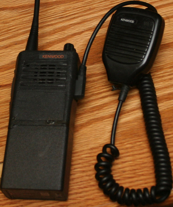 You too can walk around
like a secret service agent, police officer, or mall cop. Though there are a
number of accessories available for these radios, one of the more popular is the
external speaker/mike. The KMC-21 is shown in the photo to the left. This plugs into the side connector, and is usually
clipped to a belt, shoulder strap or epaulet. This is particularly handy for
these radios because of their size and weight. It is also helpful when operating
in harsh weather or hazardous environments, where a radio can be left safely in
its holder. This also makes it impossible to inadvertently lay the radio down
someplace and lose it.
You too can walk around
like a secret service agent, police officer, or mall cop. Though there are a
number of accessories available for these radios, one of the more popular is the
external speaker/mike. The KMC-21 is shown in the photo to the left. This plugs into the side connector, and is usually
clipped to a belt, shoulder strap or epaulet. This is particularly handy for
these radios because of their size and weight. It is also helpful when operating
in harsh weather or hazardous environments, where a radio can be left safely in
its holder. This also makes it impossible to inadvertently lay the radio down
someplace and lose it.
When the mike is plugged in, the regular speaker is cut out, and the mike serves as both a speaker and a mike. properly located, this makes it much easier to hear incoming transmissions, and less likely that you will miss something. Using an external speaker also means the radio will tend to stay more vertical, which will better align the antenna with the vertical antennas of mobile and base units. Incorrect antenna orientation can cause as much as 20 db of signal loss.
For those who really want to look cool, the external mike has a jack on the bottom, next to where the cord is connected. This jack is for an external earpiece. Plug in the earpiece, put the radio in a holder under your jacket, and get yourself a pair of sunglasses, then you too can be a secret service agent - Glock and Uzi not included.
Newer mikes for newer radios are fairly expensive, but these older units can be found for $10 - $15. I am not certain if I would have spent the money, but my radios actually came with these mikes, and I find them pretty handy. they are passive devices, and need no power other than that supplied by the amplifier of the radio.
I discuss the programming cable at length below, in the section on programming, but there is another cable that can be used to configure these radios. This is the cloning cable. The cloning cable allows you to connect two radios, and to copy all of the configuration and programming information from one radio to the other. This can be very hand in the field, or when you simply do not want to trouble yourself to set up your computer and hook it up to the radio. this is particularly handy these days, because these old radios need to be run on specially configured computers, running off of DOS boot discs in order to cable program properly. Field programming, without a cable, needs to be enabled in order to work, and can be very cumbersome. Cloning, on the other hand is easy.
To clone the TK-350, the
KCT-8 cloning cable is plugged into the external speaker port on both radios. With
both radios turned off and connected, the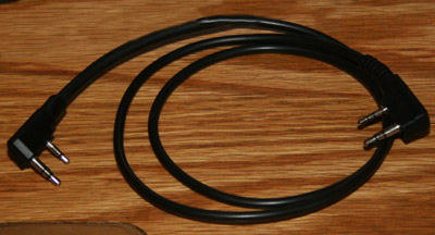 radio to be rewritten (which I will call the receive radio) should be turned on
while holding down the Lamp button (under the PTT), and the LO button on the top
panel. The LCD on the top panel will display --PC--. The radio which will send
the new configuration (which I will call the transmit radio) should be
turned on while holding the D/A key. The LCD on the top panel of this radio
should display -C-. To transmit settings, press the MON key (the key above the
PTT key) on the transmit radio. The LED on the transmit radio will flash while
data is being sent. When complete, the LCD will display END, and its LED will
stop flashing. Pressing the SCAN button will allow another radio to be cloned.
radio to be rewritten (which I will call the receive radio) should be turned on
while holding down the Lamp button (under the PTT), and the LO button on the top
panel. The LCD on the top panel will display --PC--. The radio which will send
the new configuration (which I will call the transmit radio) should be
turned on while holding the D/A key. The LCD on the top panel of this radio
should display -C-. To transmit settings, press the MON key (the key above the
PTT key) on the transmit radio. The LED on the transmit radio will flash while
data is being sent. When complete, the LCD will display END, and its LED will
stop flashing. Pressing the SCAN button will allow another radio to be cloned.
Like all professional
grade radios, the TK-350 has a number of battery and charging options. The
original KNB-11A and KNB-12A batteries had capacities of 800 mah and 1100 mah.
Today's modern aftermarket replacements provide 1200 mah to 1800 mah. A number
of drop in charger options were also offered including dual and even six unit
chargers. Rapid
 chargers can get a battery charged back up in about 90 minutes.
Standard rate chargers will get the job done overnight. Single, double, and six
unit chargers are available.
chargers can get a battery charged back up in about 90 minutes.
Standard rate chargers will get the job done overnight. Single, double, and six
unit chargers are available.
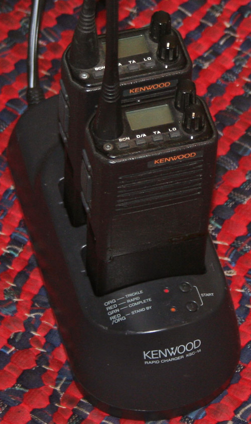
After market suppliers offer a number of different batteries, chargers, battery eliminators, and cables. A lucky break allowed me to get a KSC-14 multi unit charger (2 units) at a pretty good price. This unit is capable of trickle and fast charging, though fast charging is sometimes said to reduce battery life. The unit will charge a number of different models of Kenwood radios. I presently have three of these radios, and may get a few more, so a dual unit charger is probably a good idea for me.
Trickle recharging is the default, rapid recharging is initiated by depressing the start button. The instructions warn not to use this as a stand or a power supply for operation. This charger was designed for NiCD batteries, and I am not certain if this will cause problems with the newer NiMH types.
It would be nice if Kenwood could make a standard AA pack, that you could load with standard batteries. You could then simply charge them up yourself, and not worry about a special drop in charger, or about your pack wearing out. Or perhaps that is the reason.
Additional accessories include things like various rubber antennas, cases, belt clips, a DTMF keypad, and then the cables and software used for programming. Because these radios are well over a decade out of production, Kenwood no longer supports them. Manuals and software are available all over the web, and many aftermarket companies produce batteries and chargers. In addition, the two prong programming/external speaker jack has become standard with Kenwood, and is still being used. The antenna connector is also universal, so that Kenwood and aftermarket antennas will fit. As these radios are built like tanks, there are large numbers of them still in service, and large numbers are likely to remain in service for a long time to come.
Programming from a PC requires a KPG-22 cable, as well as the KPG 23D programming software. This is by far the best way to do it, and after having tried front panel programming, I would probably stick with the cable and the PC. You are best off with an old DOS computer. These can be had very cheaply at second hand stores. If you can not find one, or do not wish to dedicate a computer to radio programming, then you will want to get yourself a boot floppy (or boot CD) containing the MSDOS operating system, and the KPG-23D program files. Though I have been able to run the program using Dosbox, I have never been able to successfully program a radio this way. I strongly recommend using a DOS boot disc, and would not even attempt to try programming this radio from a machine running Windows.
-
A KPG-22 or compatible cable, which connects to the computer's RS-232C port. You can not use a USB cable.
-
A copy of the KPG23D programming software (this can be found in a number of places on the web, including here).
-
A computer capable of running this from an RS-232C port, as well as an operating system which can run from a DOS prompt.
-
A copy of Dosbox ( http://dosbox.sourceforge.net/
-
The TK-350 radio.
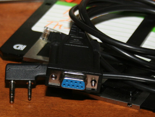 The programming cable
fits into the speaker/mike jack on the side of the radio, and then into the
RS-232C port of the computer. As this is a DOS program you can not use the USB
version of the KPG-22 cable. This cable has a two prong connector, and is often
sold as a combo cable that can also be used as a KPG-4 or KPG-46. I have
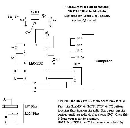
included a schematic of the cable, which includes wiring for a DB-9 and DB-25
connectors. Still, I do not recommend building one yourself, it is quite a bit
more difficult than it seems. While it is always nice to save a few dollars with
homebrew, your time is worth something.
The programming cable
fits into the speaker/mike jack on the side of the radio, and then into the
RS-232C port of the computer. As this is a DOS program you can not use the USB
version of the KPG-22 cable. This cable has a two prong connector, and is often
sold as a combo cable that can also be used as a KPG-4 or KPG-46. I have
included a schematic of the cable, which includes wiring for a DB-9 and DB-25
connectors. Still, I do not recommend building one yourself, it is quite a bit
more difficult than it seems. While it is always nice to save a few dollars with
homebrew, your time is worth something.
This is not simply an adapter cable. The cable has an IC in the base which converts the TTL signals from the radio into something that the RS-232C port can understand, and is powered by five volts taken from the connector. It is probably cheaper to just buy one, and far less difficult. These are $50 cables from Kenwood, but can are widely available in the $10 - $20 range from many aftermarket suppliers.
The KPG-23D software may be bought on disc from Kenwood, found at countless sites on the web, or downloaded from the link above. While the cables are pretty simple and foolproof, getting this software to run properly on a modern computer can be a matter of some difficulty.
With the computer turned on, the programming cable
hooked up, and the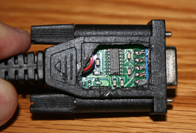
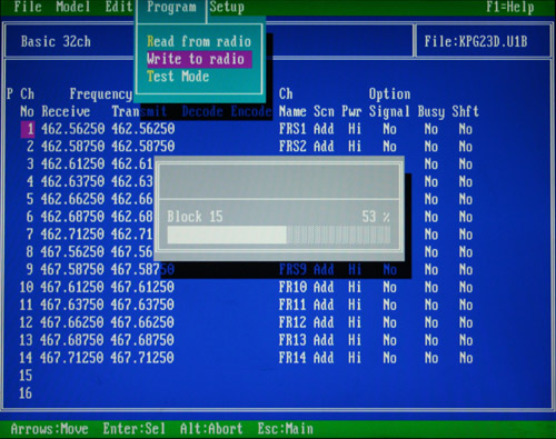
The KPG-23D program is classic DOS, there is a menu bar at the top of the screen, along with 32 channel rows (or 160 rows), and ten feature columns. Information, such as frequencies, may be typed in directly. hitting the enter key selects and moves you to the next entry. Using the space and F2 keys will access menus and change selections of features. Unlike most Windows programs, there is nothing intuitive about this, and you will need to pay careful attention, and work slowly. The help files will not be available, but the main help file, if included in your download, may be opened in Wordpad. When these radios were in production, twenty years ago, there was no Windows, and DOS was the last word in home or shop operating systems. Welcome to old time computing.
In program mode, the display should read --PC-- as shown in the photo. The photo below shows my little radio in program mode, hooked up to the programming cable, and to an AC power adapter. With the radio in this state, and properly hooked up, verify that the program is set for the correct model, and correct type. As this is a DOS program, you will not be able to use your mouse. You will need to depress the ALT key and the F key at the same time. This will get you into the menu bar at the top of the program screen. Once in the menu bar, you will need to use the arrow keys to navigate the various menus and commands.
In addition to verifying the model, you should also verify the port (com1, or com2). Once these things are set up, you may go up to the program menu on the command bar, and select Read from radio. You should see the LED on the top panel of the radio light, and your computer should now display the frequencies and other programming information. If you get an error message, check your cables, and try the other com port. You may need to try a few times to get the radio to talk to your PC. If you absolutely can not get the program to talk to your radio, I highly recommend going to the trouble of making a DOS boot disc, copying the KPG-23D files over to a floppy, and then booting the computer off of the DOS boot disc. This is the only way I have ever been able to make this program work properly, though others have claimed to be able to run it using Dosbox.
Once the program is
running, the proper model is set, and you have verified by reading that it can
talk to your radio, you can start to enter programming information. I generally
work my way across and then down, completing each channel before moving on to
the next. 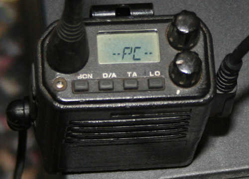 Receive
and transmit frequencies are entered separately, making any duplex split
possible. Decode and encode tones are entered by selecting from a scrollable
list accessed by hitting the F3 key.
Receive
and transmit frequencies are entered separately, making any duplex split
possible. Decode and encode tones are entered by selecting from a scrollable
list accessed by hitting the F3 key.
Setting a decode tone means that your radio will only respond to calls that contain a subaudable tone. I generally leave this off. Encode tones are used when contacting repeaters. Alpha numeric characters may be entered in the channel name column. Other selections are to enable the channel for scanning, Set the power to high medium or low (1 watt, 2 watts, 4 watts), activate signaling, and active the busy channel lock out. The last entry is for shift, and this can be a bit confusing. this has nothing to do with repeater shift, as these frequencies are set manually and individually when setting up the channel information. What the shift setting does is shift the frequencies of the internal oscillators, in case they might be interfering with reception on programmed channels. You might give this setting a try, if you hear birdies or other such things, otherwise I would leave it off.
With the main setting configured, you may wish to set up the radio features. These can be configured through the Edit menu. This is accessed by depressing the ALT and F keys and then using the arrow keys to navigate. The edit menu permits you to enable or disable the top panel buttons, and to select their functions. It also lets you set the timing and function of the scan feature, and set how tones are used and enabled.
 Other features that can be set by this menu are whether the unit can be field
programmed, what power saving features are enabled, and even the test and
internal frequencies. I generally don't play around too much with these
settings, but its nice to know they are there. Once you have set all of the
channel and frequency information, and have enabled and configured any feature
you want, it is time to program the radio.
Other features that can be set by this menu are whether the unit can be field
programmed, what power saving features are enabled, and even the test and
internal frequencies. I generally don't play around too much with these
settings, but its nice to know they are there. Once you have set all of the
channel and frequency information, and have enabled and configured any feature
you want, it is time to program the radio.
With everything entered the way you like, it is now time to write the information to your radio. This is done by hitting the ALT and F keys, and then scrolling to the Program menu. From here you scroll down to where it says, Write to radio. When you hit enter, you will be warned that current settings will be overwritten, and asked to verify that you really want to do this. Verification starts the upload of the new programming information. You will see the LED flash on the radio, and there will be a progress bar shown on the PC display. When the upload is complete, the program will advise you that the radio has been successfully programmed. Congratulations. One you have a radio set up, you may use it to clone others with the cloning cable, and may only seldom need to PC program. You can also set the radio up, via setting on the edit menu, to be field programmed. Most of the radios out there have passed through several owners by now, and are probably already enabled to do this.
Field Programming
Though the job can
be done easily and more completely using a programming cable and a PC, It is
likely that your radio is field programmable. It is an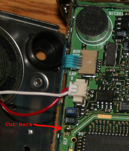 amazingly cumbersome
process, using the small LCD display and the top panel buttons and knobs. Still,
it can be done with time and patience. This will only work if the radio has been
internally modified by cutting a jumper, and if the feature has been enabled in
software. Please note that depressing the lamp and DA buttons will bring up the
SEL display, even if the radio has not been enabled, but you will not be able to
make any selections.
amazingly cumbersome
process, using the small LCD display and the top panel buttons and knobs. Still,
it can be done with time and patience. This will only work if the radio has been
internally modified by cutting a jumper, and if the feature has been enabled in
software. Please note that depressing the lamp and DA buttons will bring up the
SEL display, even if the radio has not been enabled, but you will not be able to
make any selections.
For those who love to tinker, have extra radios laying around, are made of money, or just like to live dangerously, I have included a photo to show you where to cut. As most of these radios have been through several owners by now, and have been in fleet or commercial service, there is a pretty good chance that this modifications has already been done. I should also mention that cutting the jumper alone will not make the radio field programmable. You will also need to connect to to a computer, run the KPG-23D program, and enable this feature in software.
I also feel the need to state that I am not recommending you make this modification, not holding myself as an expert on this radio, and disclaim all responsibility for you wrecking your radio. I am sorry to have to make such a statement; but as long as so many of us have absolved ourselves of responsibility for our own actions, or for anything else, and have decided to permit lawyers to rule the world, such things need to be said.
Instructions for disassembly are below. In addition to the basic disassembly, you will need to remove two tiny screws at the bottom of the front plate and then snap it loose. Once inside here, you will have access to the PC board. be very careful during disassembly, as there are many small cables and connectors.
Once field programming has been enabled, either by you or by a previous builder, The instructions below are simple enough, and will permit you to program the radio according to your requirements. Again, though you will not require a cable or PC to program, you will need one to enable the feature after the internal mod has been made.
-
Press and hold both the "Lamp" and the "D/A" buttons while turning the radio on until "SEL" is displayed.
-
Press "D/A" again and "CH 1" is displayed.
-
Press the "PTT" button. The current receive frequency will be displayed. If channel has not been programmed, display will read "---------".
-
Turning the channel knob with adjust frequency in12.5 KHz steps.
-
Pressing lamp button while scrolling frequencies will change scroll step to 1 MHz.
-
Pressing PTT button will save frequency, and advance to receive tone setting.
-
Pressing the LO button will permit setting the tone with the channel knob. Pressing the LO key again will permit setting by DCS value. Pressing PTT will save.
-
Transmit frequency and tone are now set by following the same steps as used to set receive frequency and tone.
-
Display will now read either Add or DEL. This is for including the channel in scan, and can be changed with the channel selector, and saved with PTT.
-
Display will now read On or Off for busy channel lock out. This can be changed with the channel selector, and I usually leave it off.
-
The display will now read H or L for high and low transmit power. This can be changed with the channel selector and saved with PTT.
-
Display will now read on or off for beat shift. This changes the settings for the internal oscillators, in case there is interference. I leave it off. PTT saves.
-
Repeat above steps for each channel until radio is programmed. Turning off saves.
Programming features
-
Press and hold both the "Lamp" and the "D/A" buttons while turning the radio on until "SEL" is displayed.
-
Press TA button. This will display radio type and frequency. Note that this number needs to match the type number on the back of your radio. This is adjusted using the channel selector, but should never need to be changed. PTT saves.
"UHF1" covers "450-470MHz"
"UHF2" covers "470-490MHz"
"UHF3" covers "490-512MHz"
"UHF4" covers "406-430MHz"
-
Battery saver can now be set for S, M, L or off. I usually leave mine off. PTT saves and advances to next selection.
-
Time out timer can now be set to any value between 30 and 300 seconds. This is to prevent long transmissions. I leave this off. PTT saves.
-
This selection enables or disables the scan button. Selections are scan or off. PTT saves and advances.
-
This selection enables or disables the D/A button for adding and deleting channels from scan. Selections are da1 da2 off. PTT saves and advances.
-
This selection enables or disables the TA button for the talkaround feature. Talkaround reverses transmit and receiver frequencies on duplex channels. This allows direct contact with other units on repeater channels, without having to go through a repeater. Selections are ta and off off. PTT saves and advances.
-
This enables or disables the LO button for setting high and low power. Selections are lo and off. PTT saves and advances to next.
-
This enables the monitor button, located above the PTT button. Monitor allows you to break the squelch and listen to the channel - or to signal another unit with tone. Selections are sql, off, sig1, sig2. I usually leave this on sql. PTT saves and advances.
-
This enables beep tones. Selections are on and off. When on, the unit will beep every time you make a selection or hit a button. PTT saves and advances to end.
-
Turning unit off saves all settings.
 |
This is the basic TK-350 radio unit, without its antenna or battery. These are small, though little radios. So why would anyone in their right mind want to disassemble one of these little beasts? Well, there is curiosity, and the desire to perhaps add a few improvements. Some may want to attempt to make their own repairs, though on such a small radio I would have to be pretty desperate. While poking around inside, I did accidentally find a pretty significant mod that can be made. |
 |
With the battery removed, access to the two retaining screws is easy. These are captive screws, and will not come out. Also note that the two battery contacts are held in by screws. Resist the temptation to unscrew the battery contacts. There are small rubber bumpers under the contacts that will come out and are easily lost. Unscrewing the terminal for the negative contact will permit removal of the battery mounting plate. |
 |
With the retaining screws loosened, the chassis slides right out of the top of the unit. |
 |
The service chassis removed from the case. I did this just because I like to take things apart, but I learned something very useful. If you look towards the middle of the photo, you will notice that there is a jack near the bottom of the chassis. This is a 7.5 volt input for an AC adapter. It needs a small jack with a positive tip. My 300 ma power supply was able to drive the unit on receiver, but not on transmit. Still, there are more powerful adapters out there. |
 |
Here is a shot of the reassembled unit, with a small hole drilled in the case to allow use of an external adapter. I have no idea why Kenwood never made mention of this, as it would be a very useful feature. Please note that there are a few disadvantages of making this mod. The case is very well weather sealed, and some of this integrity will be lost by drilling a hole in the case. |
|
General |
|
|
Applicable
Standards |
EIA
RS-316B: shock, vibration, humidity, dust |
|
|
7.5 V DC |
|
Channel
Spacing |
25-12.5
kHz (PLL step: 5 kHz/6.25 kHz) |
|
Dimensions
(W x H x D) |
2-17/64 x
6-7/64 x 1-13/64in (57.5 x 155 x 30.5 mm) with KNB-12A battery |
|
|
Type 1:
450 - 470 MHz |
|
Memory
Channels |
32, 160 on
the "G" model |
|
Operating
|
-22°F -
140°F (-30°C - 60° C) |
|
Weight
(approx.) |
1.2 lbs.
(545g) with KNB-12A battery |
|
Transmitter |
|
|
Audio
Distortion |
3% |
|
Channel
Frequency Spread |
Type 1: 20
MHz |
|
FM Noise |
-45 dB |
|
RF Output
Power |
4W/2W/1W |
|
Spurious &
Harmonics |
-70 dB |
|
Stability |
±0.0005%
(-30°C - 60°C) |
|
Receiver |
|
|
Audio
Output Power |
500 mW at
less than 5% distortion |
|
Channel
Frequency Spread |
Type 1: 20
MHz |
|
Intermodulation |
-67 dB |
|
Modulation |
±7 kHz |
|
Selectivity |
-70 dB |
|
Sensitivity (12dB SINAD) |
0.25µV |
|
Sensitivity (20 dB quieting) |
0.35 µV |
|
Spurious
Response |
-70 dB |
|
Stability |
±0.0005%
(-30°C - 60°C) |