The Kenwood TS-440SAT
| Overview | Working HF | Antenna | Factory Specs |
| Modifications | Computer Interfacing | IF-232C Interface | Links |
 The Kenwood TS-440 is one of the legends of ham radio. Over 600,000 of these
radios were produced in the early eighties (this number has been disputed, so I
am doing some more research - if anyone has verifiable production numbers I
would appreciate the information and the source), giving it the largest production
numbers of any HF ham radio. For its day, this was a cutting edge radio. It was
entirely solid state, including the finals; it had a pair of internal VFO's, so
that an external unit was not required for split frequency operation; it worked on all bands from 10 to 160,
and it was capable of computer control. One great feature, which has since
become standard on HF radios, is continuous receive on all SW bands. In the case
of the TS-440, all frequencies from 100 KHz up to 30 MHz can be received. With
the MARS modification, transmission on these frequencies is also possible. It
was also, for the day, compact and of light weight.
The Kenwood TS-440 is one of the legends of ham radio. Over 600,000 of these
radios were produced in the early eighties (this number has been disputed, so I
am doing some more research - if anyone has verifiable production numbers I
would appreciate the information and the source), giving it the largest production
numbers of any HF ham radio. For its day, this was a cutting edge radio. It was
entirely solid state, including the finals; it had a pair of internal VFO's, so
that an external unit was not required for split frequency operation; it worked on all bands from 10 to 160,
and it was capable of computer control. One great feature, which has since
become standard on HF radios, is continuous receive on all SW bands. In the case
of the TS-440, all frequencies from 100 KHz up to 30 MHz can be received. With
the MARS modification, transmission on these frequencies is also possible. It
was also, for the day, compact and of light weight.
Though more recent radios have offered more
features, DSP and other new technology, and easier integration with computers,
the TS-440 may have reached a point where there is nothing more really needed.
This is, for the present, the heart of my ham station.
The Kenwood covers all of the HF bands (160 through 10 meters), traditionally referred to as the Short wave bands. The bands range, roughly, from 1.8mhz to 30mhz. The Kenwood can receive continuously on all frequencies, but will only transmit into the ham bands, as it comes from the factory. There is a switch which will automatically put the radio on ham bands only, for transceiver operations, or change it over for full coverage receive only.
My particular radio has been modified to transmit continuously on all frequencies - by a former MARS user. I did not do this myself, but bought the radio in this condition. In order to stay legal, once I have been granted my general license, I will have to be careful about which frequencies I transmit on.
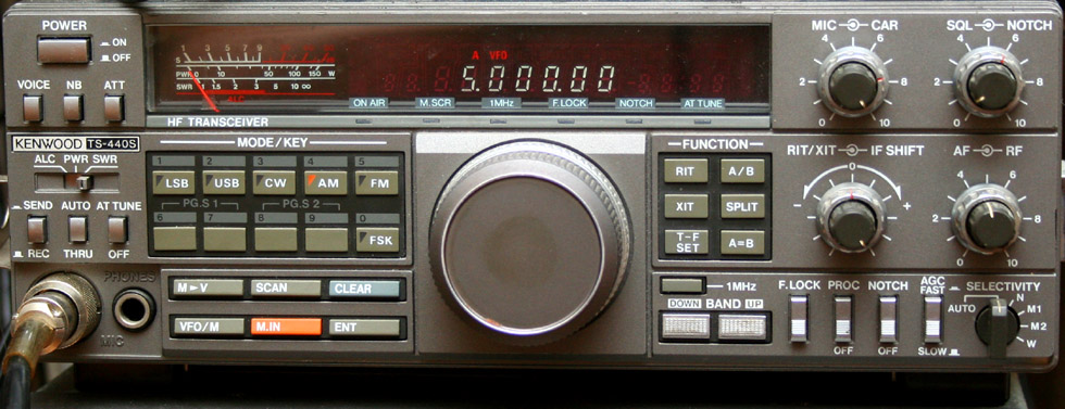
The unit was microprocessor controlled - also a big deal back in the day, and had a digital read out, and direct frequency entry, as well as the more conventional tuning dial. A CTCSS unit was available for working repeaters. There was also a voice unit for announcing frequencies and changes - very eighties. A built in auto tuner gave it the last word in multi band operating convenience, and it was rounded out by a complete line of accessories.
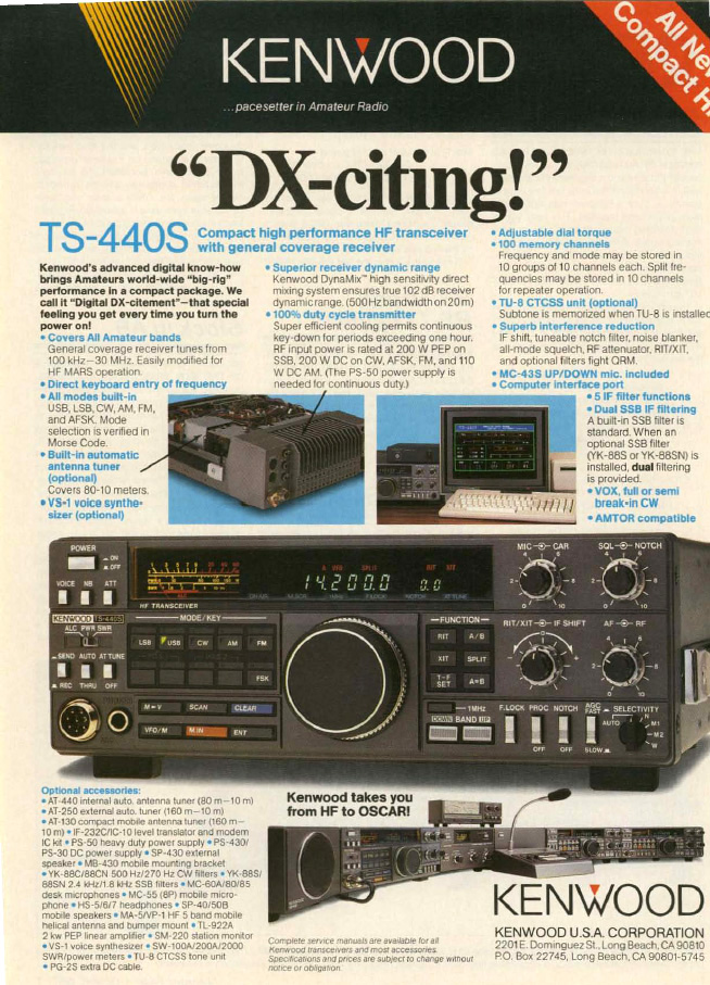
I have included an ad from the
day, taken from 73 magazine. The price new was $1200 - in 1986 dollars. This
would be well over $2000 in today's money. The filters and accessories I have
would add up to another $210. This was a top of the line, innovative radio. You can see the excitement, and the pride
of innovation, in the ad.
This is also an all solid state radio, including the finals. This is common today; but was a new thing back in the early eighties. Previously there had been hybrid radios, with some solid state components or boards; but still using tube components, usually for the finals. For the most part, solid state is far superior to tubes, though there has always been some argument from technophiles about the suitability of solid state finals. Many consider a tube final to be better sounding, with a superior signal and more flexibility than a solid state final. Audiophiles have similar feelings about hi-fi stereo amplifiers designed around tubes. Whatever truth there may be to this, solid state finals, that is to say finals that use transistors instead of tubes, are the norm these days, though tubes are still used in high power linear amplifiers.
The main advantages of solid state finals are their reduced weight and power consumption, as well as their smaller size. They are also less expensive, and lend them selves to easier production processes. In addition, a transistor is physically much more robust that a tube. A tube, with its glass body, is quite sensitive to impact, and really quite delicate. Those of us old enough to remember them also recall that tubes have a tendency to burn out. Where a transistor can last decades, or even the life of the device, tubes burned out regularly, and were designed to be replaced regularly, much like tires or brake pads on a car.
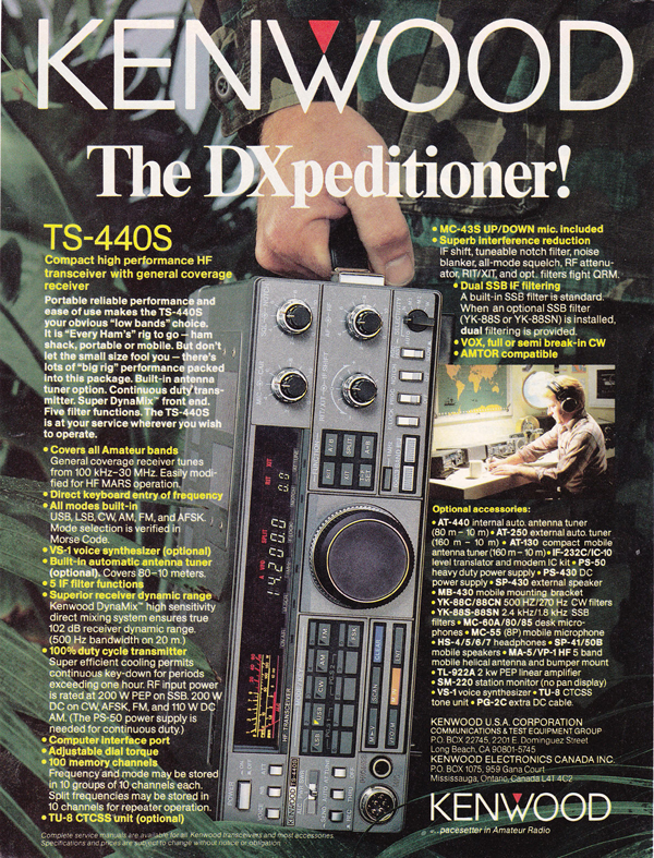
The ad reproduced to the right (love those old ads, when I can find them) indicates some of the new promise of the new all solid state radios. A full function, multiband, HF radio, that was light of weight, and could be taken anywhere and easily set up was a quantum leap. Most HF radios of the day, weighted forty or fifty pounds, compared with the fourteen to sixteen pounds of the new TS-440. Additionally, operation in the field was a rough business, and the delicate tube internals of the older style radios could be damaged, loosened, or could fail for lack of replacement tubes, should a tube burn out in the field. There was also the matter of power consumption.
The tube models tend to
use much more power. The final Kenwood hybrid (TS-520) used 5 amps when
receiving, compared to 1.9 amps on the TS-440. Pure tube radios could use even
more. Largely this was due to the need to bring a tube up to a certain
temperature, which also meant that the frequency produced by a tube final could
drift as the temperature was reached, and would also drift if the temperature
should change. So most operators would allow a warm up time (usually of thirty
minutes) for the tube finals to settle down before beginning operation. Solid
state radios
also did not require a tune up when changing bands, though with the old tube
type finals, antenna matching and SWR worries were not quite so important.
Still, there were (and are) some advantages to the old tube type finals, which I
hope to go into in another essay on this site.
The dual 2SC2879 solid state finals of the
TS-440 put out 110 watts on AM, or 200 watts on SSB.
With a good antenna system, who needs a linear? The radio is also
capable of FM operation, along with CW, and FSK. FM operation required no
optional module - another innovation. There are connections in the
back for a computer, an unnamed accessory, a terminal (for FSK), and a remote.
The unit has an antenna connector, and a built in antenna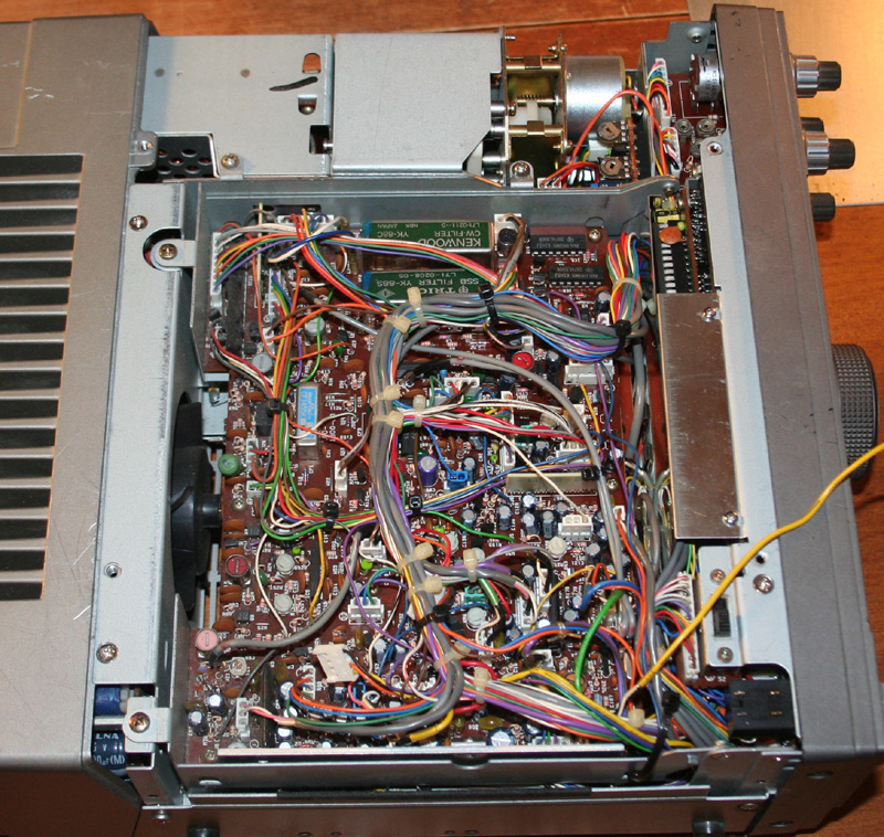 tuner. There is also a
small, built in speaker, though I will probably get an external unit, or connect
through my stereo. I was lucky, in that all of the usual add ons have been
installed by a previous owner. This includes the YK-88S and YK-88C
filters, and several internal modifications.
tuner. There is also a
small, built in speaker, though I will probably get an external unit, or connect
through my stereo. I was lucky, in that all of the usual add ons have been
installed by a previous owner. This includes the YK-88S and YK-88C
filters, and several internal modifications.
The antenna tuner worked great with my Cliff Dweller antenna, and
actually worked pretty well, when I had this unit connected to my 5/8 wave CB
antenna. I shudder to consider the inefficiency of operating through such
antennas; but it was better than nothing. Today I operate through a multi
element, bent dipole (a cobweb), which looks a bit like a nested squalo. The unit must be set to operate through the tuner, and then the AT Tune
switch is depressed. With the meter set to display SWR readings, and the antenna
tuner engaged, the needle waves back and forth for a few moments, before
settling down to the lower end of the meter. While the SWR is being adjusted,
you can hear the little motors driving the variable resistors (or whatever the
unit uses to match to the antenna). You can tell a proper match has been
achieved, when a small red LED lights, and the motors stop turning. The AT Tune switch is then released, and the
unit is all tuned, and ready to use. While the tuner is actively matching the
antenna, the unit is unable to transmit.
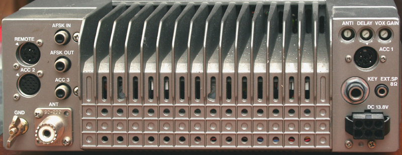
The very capable back panel of the
radio allows for a fair measure of expansion, particularly considering the
vintage of the unit. Back panel connectors include:
Right hand side
DC In - 13.8 volts nominal at 1.9a - 20a.
External Speaker - for 8 ohm connection.
Key - for 1/4" connection to key or keying device.
ACC 1 - For computer connection, when IC-10 is installed
internally.
Left hand side
Remote - For use with a linear amplifier.
ACC 2 - Data connection.
GND - To Earth ground or grounding strap.
AFSK In -
AFSK Out -
ACC 3 - Not connected/user definable.
ANT - 50 ohm antenna.
 I have installed the computer interface, and have picked up the cable, and
adapter, to run the Kenwood from Porky. I am now searching for a good software
package, and am trying to select between several. The best, offer full control
of the radio, including splits, and crossband operation. They are also able to
feed audio directly in, as well as processing audio taken directly out of the
radio. This would allow me to use many of the fax, as well as the digital mode
translation programs available. It would also allow me to do some packet radio,
and data transmission, though data transmission over ham radio is very slow
(9600 baud at maximum). One other thing I could do, is use the computer to send
and receive Morse Code. There are a number of programs which allow the user to
simply type in a message, which is then translated into Morse by the computer,
and sent out through the radio. The same programs which do this, also translate
incoming Morse Code messages into text, displayed on the computer monitor. This
is yet another reason that the current code proficiency requirement is silly. I
am presently learning visual basic, and hope to be able to write my own
controller software. While I am at it, I will attempt to make use of the various
signal processing software out there (including units providing spectrum
analyzer functions) automatic.
I have installed the computer interface, and have picked up the cable, and
adapter, to run the Kenwood from Porky. I am now searching for a good software
package, and am trying to select between several. The best, offer full control
of the radio, including splits, and crossband operation. They are also able to
feed audio directly in, as well as processing audio taken directly out of the
radio. This would allow me to use many of the fax, as well as the digital mode
translation programs available. It would also allow me to do some packet radio,
and data transmission, though data transmission over ham radio is very slow
(9600 baud at maximum). One other thing I could do, is use the computer to send
and receive Morse Code. There are a number of programs which allow the user to
simply type in a message, which is then translated into Morse by the computer,
and sent out through the radio. The same programs which do this, also translate
incoming Morse Code messages into text, displayed on the computer monitor. This
is yet another reason that the current code proficiency requirement is silly. I
am presently learning visual basic, and hope to be able to write my own
controller software. While I am at it, I will attempt to make use of the various
signal processing software out there (including units providing spectrum
analyzer functions) automatic.
I have already listened (though have not transmitted) to broadcasts from
China, Germany, Italy, and several in Spanish (Mexico, Spain, South America?).
The unit requires over 30 amps, while transmitting, though it uses only a couple
during reception. My old power supply was not up to the task, and the unit would
dim, and hum, when I attempted to transmit, or to tune the antenna. A new power
supply was ordered, providing over 40 amps, and everything is now working well.
I have only a vague idea of what to do with the assortment of buttons,
dials, and other switches on the unit, but I expect that their uses will come to
me in time. The rear of the unit is almost as complex, and capable as the front.
There are the expected connections for antenna, power, external speaker, and
ground, but there is also a collection of connectors for signal and control
processing.
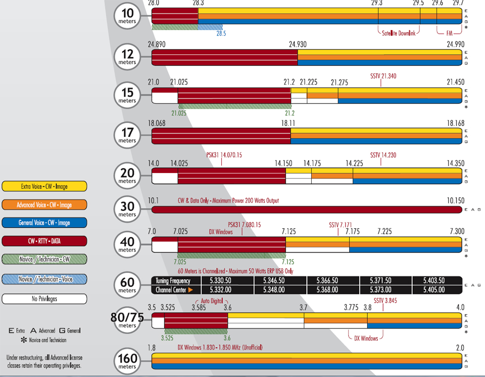
The TS-440 is an HF (high frequency) radio. There are presently 10 HF amateur bands. These bands have a total of 2.85 MHz of bandwidth. The rest of the shortwave bands are given over to commercial broadcast, military, maritime, and various other services. The TS-440 was set up for the nine bands available during its production, but the MARS/CAP modification permits access to the newer 60 meter band - though some care must be taken to transmit within band when doing this. The MARS/CAP mod is described below, but essentially permits transmissions on all frequencies within the radios' design limits.
The HF bands extend from 3 MHz to 30 MHz, and are what are commonly called the short wave bands. These are the original ham bands, and have the longest history, highest range, and largest variety of equipment. These are the bands you think of when you consider ham radio. There are the bands on which you can regularly work the entire world.
The most popular amateur mode on HF is SSB, though AM and CW (Morse Code) are also used. There are also a number of digital and fax modes available. Due to the width of its signal, FM is rarely ever seen on these frequencies, except for some use on 10 meters. A band plan is shown below. unlike band plans for VHF/UHF, the HF band plan is officially enforced by the FCC, and is a matter of international law.
Antenna systems
This is a pretty neat idea, and one of those simple solutions which makes everyone say "Why didn't I think of that ?" The Cliff Dweller is a coiled wire antenna, suited to use on 10-80 meters, though my antenna tuner seems to be able to get me occasional use on 160 meters also. The antenna itself looks like a pair of Slinkys, sprouting out from the sides of a regular balun, with a coax connection going down to the radio. The coiled wires can be used extended from 12' out to their full coiled length of 50'. This is a reasonable choice for an apartment dweller, and can be used indoors or out; very nice. A tuner will have to be
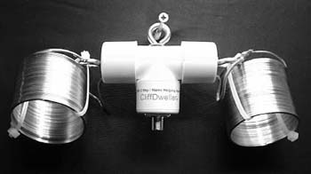 used, of
course, but this is pretty much a given for anyone attempting to use a single
antenna for multiple bands. The physical length of the wires, if they were to be
straightened out, is a full 130'. So technically, this is a coiled 80 meter
antenna. It is possible to simply buy a 130' long wire antenna, but I love the
whole idea of the Cliff Dweller, and have no wish to try and find a 130' run for
a wire antenna. I purchased the antenna from USA2WAY over the net. There are
some companies which sell knock off units, but this is the original, and is
claimed to be the best, though others make their claims too. At any rate, the
purchase also gives me a membership, of sorts, in a user group, and access to a
number of technical resources.
used, of
course, but this is pretty much a given for anyone attempting to use a single
antenna for multiple bands. The physical length of the wires, if they were to be
straightened out, is a full 130'. So technically, this is a coiled 80 meter
antenna. It is possible to simply buy a 130' long wire antenna, but I love the
whole idea of the Cliff Dweller, and have no wish to try and find a 130' run for
a wire antenna. I purchased the antenna from USA2WAY over the net. There are
some companies which sell knock off units, but this is the original, and is
claimed to be the best, though others make their claims too. At any rate, the
purchase also gives me a membership, of sorts, in a user group, and access to a
number of technical resources.
I had been reasonably happy with the antenna. It performed well enough, across most bands, and it was better than nothing. My auto tuner seemed a bit confused by it on some of the odd bands (12, 17, 30 meters), and took a bit of time to tune to it on 10 meters. With a manual tuner, the antenna tuned right up on all bands, with no problem - at least as far as visible SWR. The Cliff Dweller was initially strung along the ceiling of my apartment library, and was extended out to about 20'. I had considered running a length of wire, along the eaves of my apartment building, but did not wish to risk eviction from my building. This is the dilemma which most ham operators find themselves facing these days. It is not an easy matter to find
 space, and get permission, for a decent antenna, when living in an
apartment, or condo complex. Though these places abound with power lines, TV
antennas, and satellite dishes, most managers, and owners are poorly informed
about ham radio, and find it easier to restrict, or forbid outside antennas for
any such "non-standard" uses. The joys of city living.
space, and get permission, for a decent antenna, when living in an
apartment, or condo complex. Though these places abound with power lines, TV
antennas, and satellite dishes, most managers, and owners are poorly informed
about ham radio, and find it easier to restrict, or forbid outside antennas for
any such "non-standard" uses. The joys of city living. The Cliff Dweller is now stored away. I am, in the process of updating my antenna system, in preparation for my General license. I am stringing wires in my full and unencumbered attic (25' x 30'), to run a dual cobweb antenna system. These will be fed by twinlead, and will pass through an aircoil balun before being fed to my radio. I will put up a page about this after I finish. The first cobweb will be of traditional design, and will measure eight feet on a side. This antenna gives excellent performance on all bands from ten to twenty meters. The second cobweb will cover bands from thirty to sixty meters, and will be over twenty feet on a side. The two antenna arrays will be side by side; but the design makes them very resistant to interference with each other. One very big advantage to a cobweb is that, unlike a standard dipole, it has no nulls. These antennas lay flat in my attic, and are horizontally polarized - perfect for HF, DX, and working the various forms of skip.
For 80 and 160 meter I am considering a helical dipole, or perhaps a loaded antenna. I also may consider making due with tuning up my 40 or sixty meter portions of my cobweb. Between the air coiled balun (very near the transceiver), and the low loss of my twinlead feed, this may be possible without too much compromise in efficiency. When resonant, these antennas are said to be 95% efficient. When combined with twinlead and a good balun, the efficiency of the entire system can be as high as 90%, or perhaps a bit higher.
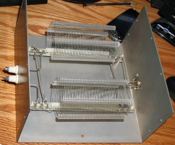
The balun is an classic Heathkit model, and is of a type not much in favor these days. Air coil baluns are larger than today's solid core units; but in many ways
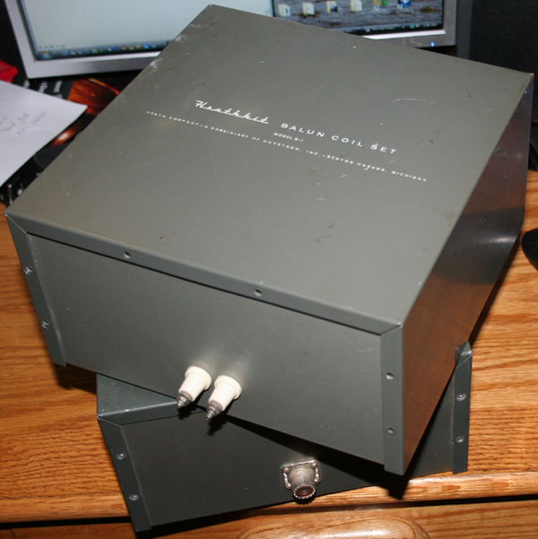 are much better.
They do not
heat up, and allow for a bit more flexibility. This particular design, with the
twin coils in a case, and a twin lead connector on one end and a standard coax
connector on the other, permit me to use my
radio's internal auto tuner.
are much better.
They do not
heat up, and allow for a bit more flexibility. This particular design, with the
twin coils in a case, and a twin lead connector on one end and a standard coax
connector on the other, permit me to use my
radio's internal auto tuner.One very nice thing about these balun boxes is that they can be easily set to 1:1 or 1:4. It appears that a 1:1 setting will work best for a cobweb. This is because a cobweb has a native impedance of 48 ohms. For information on why this is true, visit my cobweb antenna page (when it is finished). It is basically a bent dipole, which should have a native impedance of 12 ohms. Making the elements of twin lead, and then shorting the twin lead at a particular point turns this into a folded dipole, as well as a bent dipole. This quadruples the impedance to 48 ohms. Thus, no impedance matching must be done by the balun; It need only function as a choke. With twin lead feedline, even this is almost not needed.
I had purchased a G5RV; but it is not very efficient on most bands, and also has a strange radiation pattern on the higher frequencies. it also requires at least 70 feet of coax to be run as feed line. This tells me that the antenna is radiating off of its coax shield, which can be a source of TVI, and can give an even stranger pattern. I will probably end up using it as the platform for my multi fan dipole short wave receiver antenna. In a receiver, such things are not quite as important, particularly if there are a number of other antenna elements.
The G5RV has an efficiency that varies according to band; but is never much higher that 25%. Only at 20 meters, and perhaps 80 meters, is the antenna even remotely efficient. I know these are fighting words for many who consider this antenna a legend, but the proof is at: http://vk1od.net/antenna/G5RV/index.htm .
| Modes | LSB (A3J), USB (A3J), CW (A1), AM (A3), FM (F3), FSK (F1) | ||
| Antenna Impedance | With AT Unit | 20 to 150 Ohms (Transmit Only) | |
| Without AT Unit | 50 Ohms | ||
| Grounding | Negative | ||
| Power Requirements | 12 to 16 Volts DC (13.8 VDC Reference) | ||
| Current Drain | Receive Mode with no input | 1.9 amps | |
| Transmit Mode | 20 amps | ||
| Operating temperature | -10 to +50 C (+14 to +122 F) | ||
| Dimensions | Wide
High Deep |
270mm (279mm)
96mm (108mm) 313mm (335mm) |
|
| Weight | With AT Unit | 16.1 Pounds | |
| Without AT Unit | 13.9 Pounds | ||
|
|
|||
| Frequency range | 160 Meter Band | 1.8 to 2.0 MHZ | |
| 80 Meter Band | 3.5 to 4.0 MHZ | ||
| 40 Meter Band | 7.0 to 7.3 MHZ | ||
| 30 Meter Band | 10.1 to 10.15 MHZ | ||
| 20 Meter Band | 14.00 to 14.35 MHZ | ||
| 17 Meter Band | 18.068 to 18.168 MHZ | ||
| 15 Meter Band | 21.00 to 21.45 MHZ | ||
| 12 Meter Band | 24.89 to 24.99 MHZ | ||
| 10 Meter Band | 28.0 to 29.7 MHZ | ||
| Input Power | LSB, USB, CW, FM, FSK | 200 Watts PEP | |
| AM | 110 Watts PEP | ||
| Modulation | LSB, USB | Balanced Modulation | |
| FM | Reactance Modulation | ||
| AM | Low Level Modulation | ||
| Spurious radiation (CW) | Less Than -40 db | ||
| Carrier Suppression | More Than 40 db (With 1.5 KHZ Reference) | ||
| Unwanted Sideband Suppression | More Than 50 db (With 1.5 KHZ Reference) | ||
| Third Order Distortion | More than 26 db below one of two tones | ||
| Maximum Frequency Deviation (FM) | 5 KHZ | ||
| Frequency Response (-6 db) | 400 to 2600 HZ | ||
| Microphone Impedance | 500 Ohms to 50k | ||
|
|
|||
| Circuitry | Triple Conversion Superheterodyne | ||
| Frequency range | 100KHZ to 30 MHZ | ||
| Intermediate Frequency | 1st: 45.05 MHZ, 2nd: 8.83 MHZ, 3rd: 455 KHZ | ||
| Sensitivity | LSB, USB, CW, FSK
(At 10 db S/N) |
100 to 150 KHZ | Less Than 2.5 uV |
| 150 to 500 KHZ | Less Than 1 uV | ||
| 500 KHZ to 1.6 MHZ | Less Than 4 uV | ||
| 1.6 to 30 MHZ | Less Than 0.25 uV | ||
| AM (At 10 db S/N) | 100 to 150 KHZ | Less Than 25 uV | |
| 150 to 500 KHZ | Less Than 13 uV | ||
| 500 KHZ to 1.6 MHZ | Less Than 40 uV | ||
| 1.6 to 30 MHZ | Less Than 2.5 uV | ||
| FM (At 12 db SINAD) | 1.6 to 30 MHZ | Less Than 0.7 uV | |
| Selectivity | LSB, USB, CW, FSK | -6 db | 2.2 KHZ |
| -60db | 4.4 KHZ | ||
| AM | -6 db | 6 KHZ | |
| -50 db | 18 KHZ | ||
| FM | -6 db | 12 KHZ | |
| -50 db | 25 KHZ | ||
| Image Ratio | 100 KHZ to 1.6 MHZ | More Than 50 db | |
| 1.6 MHZ to 30 MHZ | More Than 70 db | ||
| IF Rejection | 100 KHZ to 1.6 MHZ | More Than 50 db | |
| 1.6 MHZ to 30 MHZ | More Than 70 db | ||
| IF SHIFT Variable range | More than 0.9 KHZ | ||
| RIT/XIT Varaible Range | More than 1 KHZ | ||
| Notch Filter Attenuation | More Than 20 db (at 1.5 KHZ) | ||
| Squelch Sensitivity | LSB, USB, CW, FSK | 100 to 150 KHZ | Less Than 20 uV |
| 150 to 500 KHZ | Less Than 10 uV | ||
| 500 KHZ to 1.6 MHZ | Less Than 20uV | ||
| 1.6 to 30 MHZ | Less Than 2 uV | ||
| FM | 1.6 to 30 MHZ | Less Than .32 uV | |
| Output | 1.5 Watts at 8 Ohms (10% Distortion) | ||
| Output Load Impedance | 4 to 16 Ohms | ||
| Frequency Accuracy | Less than .00001 error | ||
| Frequency Stability | Less than .00001 error | ||
Mods
A number of features may be changed/added, by clipping or inserting diodes on the control board. You may have seen these on other places on the net, but I include them here for reference:
Diode options: There are a bunch of configuration options controlled by clipping or inserting diodes on the back of the control board. You get to it by taking the top and bottom covers off (a bunch of silver screws), loosening the front panel (4 flat-head silver screws, NOT the black ones). Then you have:
| diode | controls | in | out (cut) |
| D65 | mode confirmation | Morse | single beep |
| D66 | display resolution | 100 Hz | 10 Hz |
| D67 | memory protect | none | on |
| D73 | CW shift | 800 Hz | 400 Hz |
| D78 | WARC 24MHx band tx | disabled | enabled |
| D79 | WARC 18MHz band tx | disabled | enabled |
| D80 | General Coverage tx | disabled | enabled |
- Display has been set to indicate frequency down to 10 Hz
- Continuous coverage transmit, from 100Khz to 30 Mhz
- Computer control, and connection to Porky
- Computer signal interface, allowing computer processing of transmitted, and received signals.
Opening the radio and performing mods.
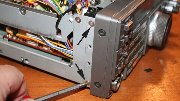 |
Remove top and bottom covers. In addition to being a requirement for mods, it gives a chance to look around the inside of the radio. Once these are removed, remove countersunk silver screws (two on each side), holding control panel on chassis. Do not remove the black screws holding the front face on. Then GENTLY - pull control panel away. You only need to pull it away a fraction of an inch. Be as careful as you can. There are a million tiny wires there. |
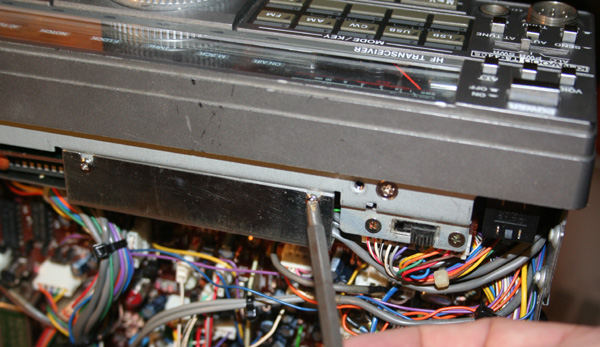 |
Remove screws from shield, so that shield can be removed from the front panel assembly. There will be a pair of round head screws on the top, and a trio of roundhead screws on the bottom. Gently rock and slide the heat shield out. |
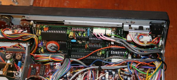 |
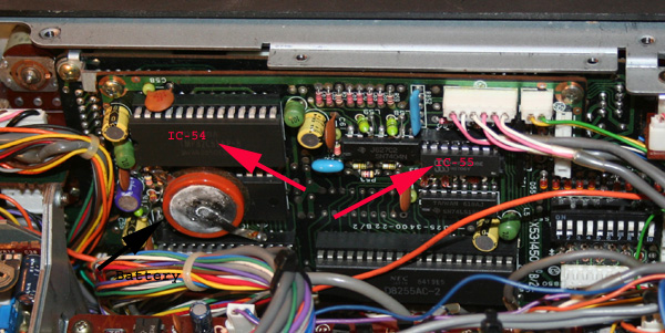
The front panel with the heat shield removed. The back up battery to the left of the photo is just under IC-54. Note the dip switch to the right of the photo. Just underneath this dip switch are the diodes that can be cut or jumpered to enable features and enhance the radio. |
 |
Place IC chips in sockets. These are shown filled, as might often be the case. These radios have been around for thirty years, and many have been modified and enhanced. Be very careful to line up the notches properly. You may need to do a processor reset after installation. |
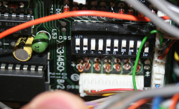 |
A close up of the dip switch and the diodes. There is also a row of diodes above the dip switch, but I have been unable to find any documentation for what they might affect. Though the manual and a number of sites on the web give directions on cutting or jumpering diodes, the manual warns not to change the dip switch settings. |
The control interface is a convenience, and allows for easy programmed operation, as well as an almost unlimited number of memories. A signal interface (also known as a data interface) will open up a whole new world. Once a signal interface is installed, the ham operator will have full access to:
- RTTY
- Packet
- Fax
- SSTV
- FSK
- Direct digital (computer to computer)
The internal modifications consist of the installation of a pair of chips. These are shown in the schematics as IC 54 and IC 55, and install easily into sockets already present in the radio, on the back of the control unit circuit board. These chips can be bought, with instructions, from Kenwood as the IC-10 Interface Kit, or as kits by aftermarket retailers; they can also be bought via mail order, or at any good electronics store:
IC 54 is a uPD-8251-AC Serial Communications Interface.
Commonly called an 8251A
IC 55 is a TC-4040-BP 12 Stage CMOS Divider.
Commonly called a 4040
Installation of these chips enables an ASCII interface (TTL levels). This interface is accessible through the 6-pin DIN connector ACC-1 on the rear of the unit. Though this may be connected directly to certain computers, or through certain interface cards, most users will need the addition of an outboard converter box to connect to the more common RS232C port. With the IC-10 interface, or equivalent, installed, the output at ACC-1 is as follows:
Signals are TTL levels (NOT RS-232)
Baud rate is 4800 (1200 Opt.)
Format is ASCII Serial; 1 Start, 8 Data, 2 Stops
The Baud rate may be changed to 1200 Baud by removing jumper W50 and installing a jumper from the left pad to the center pad as viewed from the front of the radio. This will become obvious once you have the radio opened up. Many other Baud rates are possible, just look at the schematic.
 integral control interfaces and extensive software suites, are not directly or
easily adapted to run a signal interface. A signal interface is simply a way to
run your radio's output into your computer, rather than directly through a
speaker, and take an input directly from a computer, rather than only through a
mike. Once this is done, a whole new world of possibilities opens up. It is not
so much that it is impossible to install a signal interface, but rather, all of
the current methods are a bit cumbersome. Most involve a hodge podge of cords,
cables and converters, running from the computer's sound card to the input, and
output jacks of the radio. There would then be another set running from the
serial port to the PTT circuit, unless there is already a control interface
installed to perform this function.
integral control interfaces and extensive software suites, are not directly or
easily adapted to run a signal interface. A signal interface is simply a way to
run your radio's output into your computer, rather than directly through a
speaker, and take an input directly from a computer, rather than only through a
mike. Once this is done, a whole new world of possibilities opens up. It is not
so much that it is impossible to install a signal interface, but rather, all of
the current methods are a bit cumbersome. Most involve a hodge podge of cords,
cables and converters, running from the computer's sound card to the input, and
output jacks of the radio. There would then be another set running from the
serial port to the PTT circuit, unless there is already a control interface
installed to perform this function.
Digital technology has moved so fast, over the last couple of decades, that radio manufacturers can be forgiven for failing to recognize the coming advances, and the potential of running signals through a computer. Up until the last dozen years or so, the average home computer was just not powerful enough to do much, in regards to processing audio signals, or extracting digital information from them. The early units also tended to be expensive, and to need expensive interface cards. Sound cards, as we know them today, were almost unheard of before the mid nineties. The early sound cards were also difficult to install, temperamental, and could be hard to add outside devices to. I know this from personal experience, because, in the early nineties I attempted to get digital audio into my old Windows 3.1 computer, a frustrating and fruitless effort.
There are three ways to
get a clean signal from and to, the TS-440. When I say clean signal, I mean a
signal that is at a steady level, and not affected by user settings. They are
from the FSK jacks, the ACC-2 13 pin connector (shown above), and the remote
connector. FSK jacks were meant to be connected to dedicated terminals for
teletype style communications. The FSK connectors are the easiest to use, because
they require standard RCA style jacks. The remote connector was meant for use
with a linear amplifier, and the ACC-2 was designed for data connection. The
remote is suitable only for reception, and it's receiver in pin was set up to
permit a reception path that did not pass through the amplifier.
Of the three, the obvious first
choice would be ACC-2, even though it will require purchase of construction of a
special cable and connector. It has two great advantages over the FSK
connectors. Though both have a clean 300 mv signal on output, untouched by AF
gain, cw sidetone, feeper, or voice response unit, input is a bit different. On
input AFSK and microphone signals both go through the mike preamp and speech
processor. On data they do not, though they are controlled by the mic level
control, which can aid in adjusting levels to match your sound card. There is
also a Mic mute/PTT function. This is nice because it allows you to keep your
microphone connected, and do not have to manually key PTT.
IF-232C
The outboard converter box changes the signal from TTL to the more common RS232C serial form, adapting the voltage, and acting as a noise suppresser. It
 also adapts the six pin DIN connector to the more common D
connector used by the RS232 port. Kenwood calls it's model of outboard converter
the IF-232C. The outboard converter is plugged into ACC-1 on the back of the
radio, presuming that the IC-10 or equivalent has already been installed. The
computer may then be plugged in, via an RS232C port, to the converter box, and
suitable software installed. The radio may now be completely controlled via
computer.
also adapts the six pin DIN connector to the more common D
connector used by the RS232 port. Kenwood calls it's model of outboard converter
the IF-232C. The outboard converter is plugged into ACC-1 on the back of the
radio, presuming that the IC-10 or equivalent has already been installed. The
computer may then be plugged in, via an RS232C port, to the converter box, and
suitable software installed. The radio may now be completely controlled via
computer. These have not been produced by Kenwood in years, but are widely available from third parties. the most popular units are those made by PIEXX. Some companies produce simple adapter cables; but many of these do not include the required isolation circuitry.
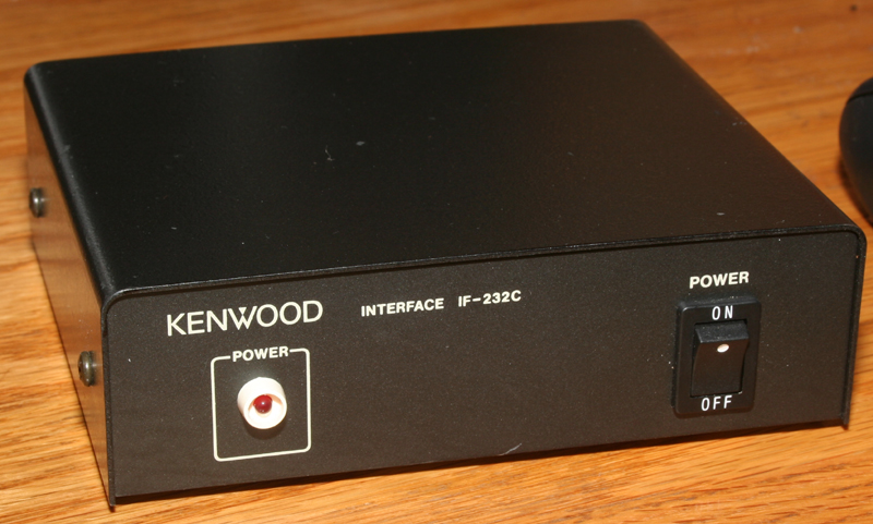
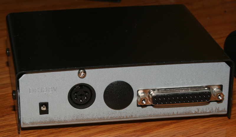 I have a traditional IF-232C outboard
controller, made by Kenwood in the eighties. it is smaller than it appears in
photos, measuring 5.2 x 1.5 x 4.5 inch. The unit
requires 13.8 VDC @ 150 Ma. In addition to matching levels, the box also serves
as an optoisolator. It is compatible with all of the Kenwood radios from the
eighties and nineties. This includes the TS-440, the TS-811, the TS-711, and the
TS-60s. IT is also compatible with the SW receivers made in the eighties and
nineties. The back of the unit has connectors for the power adapter, a standard
D25 connector for connection to a computer, and a round six pin connector
for hooking up to the ACC1 port on the radio. There is also a covered
opening for future expansion.
I have a traditional IF-232C outboard
controller, made by Kenwood in the eighties. it is smaller than it appears in
photos, measuring 5.2 x 1.5 x 4.5 inch. The unit
requires 13.8 VDC @ 150 Ma. In addition to matching levels, the box also serves
as an optoisolator. It is compatible with all of the Kenwood radios from the
eighties and nineties. This includes the TS-440, the TS-811, the TS-711, and the
TS-60s. IT is also compatible with the SW receivers made in the eighties and
nineties. The back of the unit has connectors for the power adapter, a standard
D25 connector for connection to a computer, and a round six pin connector
for hooking up to the ACC1 port on the radio. There is also a covered
opening for future expansion.Internally, the unit is pretty simple, by today's standards. A single circuit board holds the optoisolators, a couple of chips for the RS-232, and the various
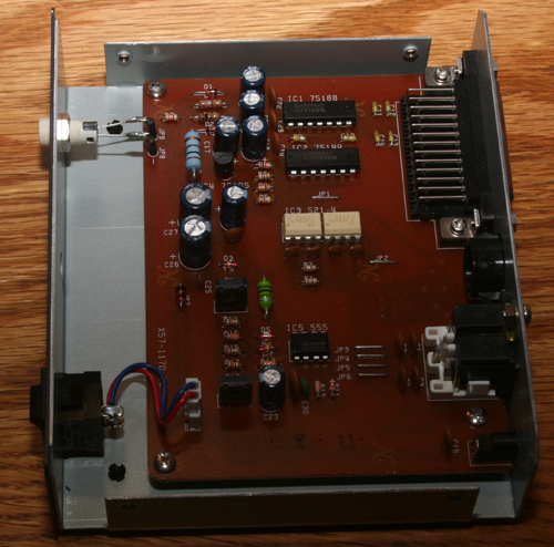 transformers, capacitators, and
regulators needed to provide them with correct voltages. The IF-232 Interface
from Kenwood is a 1488 and a 1489 chip in a box. These are an RS-232 Quad Line
Driver and Receiver. The 1488 needs 12 vdc + and - supply. The 1489
requires +5 vdc. These lead out to a standard Kenwood six pin connector. A close
look at the board, just above the six pin connector shows what look like circuit
traces and holes for the installation of another six pin connector, along with
the caps that are used as buffers. This is right by the placement of the plugged
hole in the back of the unit. I am not certain if this was ever intended to run
more than one unit, and how the two units might be switched (perhaps in software
by unique radio identifiers)" but this holds out some interesting possibilities.
transformers, capacitators, and
regulators needed to provide them with correct voltages. The IF-232 Interface
from Kenwood is a 1488 and a 1489 chip in a box. These are an RS-232 Quad Line
Driver and Receiver. The 1488 needs 12 vdc + and - supply. The 1489
requires +5 vdc. These lead out to a standard Kenwood six pin connector. A close
look at the board, just above the six pin connector shows what look like circuit
traces and holes for the installation of another six pin connector, along with
the caps that are used as buffers. This is right by the placement of the plugged
hole in the back of the unit. I am not certain if this was ever intended to run
more than one unit, and how the two units might be switched (perhaps in software
by unique radio identifiers)" but this holds out some interesting possibilities.The DB-25 connector that goes to the computer RS-232C port is not as common as it once was. At one time, it was standard for most computers to have a pair of com ports, one with a DB-25 and one with a DB- 9. If you happen to have a computer set up in such a fashion, then a standard DB-25 cable will work. Otherwise you will need a DB-25 to DB-9 com cable - also pretty common. Today, the DB-25 is used almost entirely for the printer port, with the com port using a DB-9. Even this is not so common any more. Most computers use USB exclusively these days. A really new computer may need either a USB converter, or a com card.
Six Pin Signal Comments
_______________________
1 Gnd Signal Ground
2 TXD Serial Data from Radio to Computer
3 RXD Serial Data from Computer to Radio
4 CTS Computer Ready; (Radio Input)
5 RTS Radio Ready; (Radio Output)
6 No Connection
Pins 4 and 5 may be left Unconnected.
For those that need to make a cable to convert DB-25 to DB-9, I have included pinout info below. As always, I recommend just buying the cable, as they are cheap enough, and making one can be a pain. Still, for those who want to homebrew, here it is:
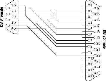
| DB9 | DB25 | Function |
|---|---|---|
| 1 | 8 | Data carrier detect |
| 2 | 3 | Receive data |
| 3 | 2 | Transmit data |
| 4 | 20 | Data terminal ready |
| 5 | 7 | Signal ground |
| 6 | 6 | Data set ready |
| 7 | 4 | Request to send |
| 8 | 5 | Clear to send |
| 9 | 22 | Ring indicator |
The manual for the IF-232C is available here.
A number of software packages are available, and I go into
a bit more detail on my page about Porky the computer.
However, once you have gotten your signal interface, and your control interface
set up, you might want to try the DXLAB series of freeware. This is a series of
applications which are able to run your computer, log your contacts, calculate
usable frequencies for specific locations, and determine propagation affects of
sunspots. These programs can also generate great looking maps, and display your
contacts on them, decode, and encode RTTY, and PSK, and who knows what else. The
whole suite can be found at:
http://www.qsl.net/dxlab
| Computer interface | Eham review of TS 440 | Raymond Sario LCU-3 cable | signal interface |
| Hosenose interfaces | Donners signal interface | Manual | Tips and Tricks |
| Service manual |