The Uniden Washington
| Manual | Antenna | Specs |
| Repair | Schematic | Links |
Top Drawer
Back in the day, as so many old timers like to say, this was one of the most sought after radios on the market. In point of fact, this radio was introduced in 1983, at a time to ride the crest of a wave that was about to recede. The day was the late 1970's to mid 1980's, when nearly everyone was caught up in what has come to be called the CB Craze. The old line companies like Radio Shack, Midland, and Johnson were cranking out CB radios as quickly as they could be manufactured, subcontracted, or imported. They were joined by nearly everyone else. Sears, JC Penny, and Montgomery Ward had their own CB lines, as did Sony, G.E., RCA, and just about anyone who dealt in any way with electronics. Still, the holy grail of radios were the Cobras by Dynascan, and the President series by Uniden.
The acclaim may have been little more than hype. After all, nearly every CB radio offered by all the different companies were made in three or four factories in Korea, Japan, and perhaps Singapore or the Philippines. As an example, it is widely known that the Cobra 142GTL is the same radio, internally, as the Uniden Washington. So why buy one over the other? The Cobra 142GTL has its controls mounted console style, while the Uniden is more straightforward. Styles, finish, and claims of better quality control might make a purchaser choose one over the other.
For those who missed the great CB Craze of the seventies and eighties, I have to advise you that there really was little difference between the various radios other than style, features, and advertising. The reason for this was the FCC. The FCC stringently regulated output levels, signal purity, and spurious emissions on CB radios. The specs from one radio basically could be applied to every other radio. Now it was possible to have some radios with a better receive section than others. But all transmitter sections were basically created equal. Those who bragged that certain radios had more swing than others, were either over modulating with power mikes, had done illegal modifications, or were just plain lying.
Keeping all the above
mentioned in mind, this is a great CB radio. It does all 40 channels, and is
also capable of both AM and SSB operation. It has a channel nine emergency
button, which was a big deal back in those pre cell phone days, as well as a
noise blanker, and some other interesting gadgets. One big feature is the mic
gain knob, which cuts in a built in preamp. Its a nice feature for use with a
standard microphone, and dispenses with the worry that your amplified mic might
have a dead battery. There is also an RF gain knob, though electrically this is
more like an RF attenuator control. This adjusts the sensitivity of the front
end. Back when these radios were made, and CB was in its glory, channels were
busy and there was a lot of traffic. It was sometimes necessary to deafen the
receiver a bit to prevent it from being overloaded. Sadly, such a feature is no
longer needed.
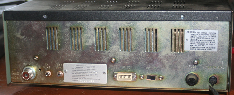
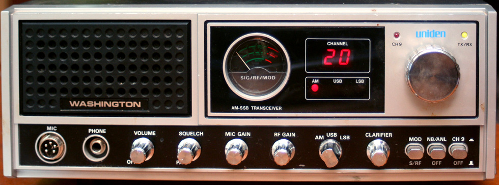
The front panel has connectors for the once common 1/4 inch headphone jack (now largely replaced by the 1/8" jack), as well as a five pin microphone connector, and the various control knobs for the channels, modes, and features. It also houses the channel indicator, meter, and modulation/RX LED. The back panel holds connectors for AC, DC, an antenna connector, a fuse holder, and then an external speaker and PA speaker.
This is an SSB radio. When I became a ham operator, I promised myself that I would never buy another AM only radio. For those not familiar, SSB CB radios are sometimes called 120 channel radios, due to being able to operate in three modes on each of their 40 channels. There is the upper and lower sideband, and then the regular AM mode on each channel. This isn't truly like having 120 discreet channels. When operating on sideband, a channel is unusable for AM. The real reason to have SSB is for the extra power that it can produce. Squeezing four watts into a single sideband, without using any of it for the AM carrier, or the other sideband, essentially triples your power. This does not come without a cost. SSB radios are more sophisticated and expensive, they also take a bit of practice to use. A clarifier control is required to tune the channel to the sideband.
There were three different version of the Washington radio made. The original was from when the President CB company was still independent. the second was right after the company was purchased by Uniden, and the third was the final version after Uniden made it their own. There are various argument over which version is the best. I personally like having the final version, others say the originals were best. No one seems to have much love for the transitional version. The basic differences between the three were:
-
The first generation carried the President Label and used the 858PLL. This model also had the four pin microphone jack.
-
The second generation also carried the President Label, used the same inside components but added a channel 9 button and an LED for the channel 9 indicator under the channel display. It also added a PA feature on the squelch knob.
-
The third generation was the Uniden it utilized the MB8719PLL. The Uniden had a 5 pin microphone jack (speaker will not work if microphone is not plugged in).
Technically the CB band is a SW (HF) band. Ham operators used it in just this manner, back before it was taken from them in the fifties and turned over to the CB service. CB usage was designated by the FCC as being for short range mobile/base communications using vertical antennas. Typically, this is the type of use for which UHF and VHF bands are generally employed, and for very good reason. The higher VHF/UHF frequencies are very limited in range, generally to what is called line of sight. HF frequencies are capable of bouncing around a bit and can end up anywhere in the world. To keep CB communications local, the FCC limited power to four watts. This does not always work, as the many CB operators who work skip will tell you. The UHF/VHF bands also require much shorter antennas than the HF frequencies.
This presents some problems when setting up an antenna. A typical HF antenna is horizontally polarized - that is to say it lays on its side. This is ideal for long range, SW type of communications. The typical UHF/VHF antenna made for local communications will be vertically polarized - that is to say it will stick straight up in the air. As a SW band, the 16' long wire that could be used for these frequencies is not much of a problem, you can put it anywhere. As a local band, the 9' to 17' high antenna can be a problem. I am a limited space (read stealth) operator, and am unable to erect any really big antennas.
Initially, this set was operated on a horizontal dipole - probably the worst kind of antenna to use for CB, unless you are chasing skip. A horizontal dipole has nulls at both ends, so your antenna will be deaf out the ends. It will also push a big portion of your signal into the ground, and another big portion right up into the sky. This doesn't leave much. To make matters worse, since the antenna is horizontally polarized, and most CB antennas are vertically polarized, there is something like 20 db of loss due to polarity differences. The only advantage to a horizontal dipole is that it is easy to build and mount. It is essentially a pair of quarter wave long pieces of wire, strung out in opposite directions. I eventually ended up turning this antenna into a vertical dipole.
You don't hear much
about vertical dipoles, and for a while I thought, as do most people, that there
was no such thing, or that such an antenna was so poor that it was unusable.
Vertical dipoles have some conditions under which they must be used; but once
this is understood, they are great performing antennas. The main thing to keep
in mid is that a dipole is rather sensitive to its height above ground, and a
vertical dipole is much more so. At just over a quarter wavelength in elevation,
the signal of a vertical dipole will launch itself out at an angle of almost
fifty degrees. This angle will drop as elevation continues to increase; but will
not be at a good angle for local communication until the antenna height is in
excess of any tower a normal person has the funds to build. So the big secret is
to keep the antenna height below a quarter wave, or get it up above several
wavelengths or more. For eleven meter (CB frequencies), this means keep it below eight feet
or above eighty.
The other problem with a vertical dipole is that unless you are over a perfect ground, there is little or no gain. This is the main reason that most people use a ground plane - that is an artificial ground, when raising vertical antennas. The other option is to use a tuning or matching stub, basically turning your vertical dipole into an end fed J-Pole. I have J-pole antennas; but for CB it would need to be about 24 feet high. this won't work for me. Presently, in the warmer months, I use the old vertical dipole, hanging from the side of my house. In the winter I have a far less efficient indoor antenna which just about fits in my attic.
In general, I share the antenna used by my Console V. More details about my solutions to the dilemmas faced by stealth user will be found on that page. I never have both radios on at the same time. One of the worst antennas I have ever used was one of those little back of the set units. Interestingly, there is not as much loss with one of these as you might think. Since most loss occurs in the feed line, and there is no feed line with a back of set antenna, there is no transmission line loss. Unfortunately, these antennas are such a small fraction of a half wave that they have an efficiency of only a couple percent.
|
Model |
Uniden Washington |
|
Frequency Range |
26.965 - 27.405 MHz (40 Channels) |
|
Emission Modes |
AM/USB/LSB |
|
Frequency Control |
Phase Lock Loop (PLL) Synthesizer |
|
Frequency Tolerance |
0.005 %** |
|
Frequency Stability |
0.001 %** |
|
Operating Temperature Range |
-20°C to +50°C** |
|
Microphone |
Dynamic PTT, 500 Ohms 5 pin |
|
Input Voltage (DC/AC Selectable) |
13.8V DC / 110V AC 60Hz |
|
Current Drain: Transmit (AM full mod.) |
< 3.0A** |
|
Current Drain : Receive (Squelched) |
£ 0.3A** |
|
Current Drain : Receive (Max. audio output) |
< 1A** |
|
Antenna Connector |
UHF; SO239 |
|
Dimensions |
5"H x 13.5"W x 11"D |
|
Weight |
13 lb.** |
|
TRANSMITTER |
|
|
RF Power Output |
AM : 4W / SSB : 12W PEP 2sc1306 |
|
RF Transmit Modes |
AM/SSB |
|
Modulation |
High and Low level Class B, Amplitude Modulation : AM and SSB |
|
Spurious Emissions |
-60 dB** |
|
Carrier Suppression |
-45 dB** |
|
Audio Frequency Response |
300 to 3000 Hz** |
|
Antenna Impedance |
50 Ohms |
|
Output Indicators |
Meter shows RF output power, and AM Modulation level. Transmit LED glows red when transmitter is in operation. |
|
RECEIVER |
|
|
Sensitivity for 10dB S/N (AM/ SSB) |
< 0.5 mV / < 0.25 mV** |
|
IF Frequency |
AM: 10.695 MHz 1st IF, 455 KHz 2nd IF |
|
Image Rejection |
-60 dB** |
|
Adjacent Channel Selectivity |
-55 dB** |
|
RF Gain Control |
45 dB adjustable for optimum signal reception** |
|
Automatic Gain Control (AGC) Figure of Merit |
100 mV for 10 dB Change in Audio Output** |
|
Squelch |
Adjustable; threshold less than 0.5 mV** |
|
Noise Blanker |
RF type** |
|
Audio Output Power |
2.5W @ 10% THD** |
|
Audio Frequency Response |
300 to 2500 Hz** |
|
Built-in Speaker |
8 Ohms, 4 Watts** |
|
External Speaker (Not Supplied) |
8 Ohms, 4 Watts** |
Extra channels/Increased power
(breaking the law, and wrecking your radio)
Lots of mods on these radios - too many. That is probably one of the reasons for their popularity. The following mods are stolen from other web sites, and are all legal, as far as I know. The illegal modifications for transmitting out of band (a very popular mod for this radio) are not included, though they may be found in various places on the web.
POWER TWEAKS
(Mike circuit changes:)
1. UNSOLDER banded end of diode D21 and lift up.
2. UNSOLDER banded end of diode D22 and lift up.
3. SOLDER a 4.7 k resistor across where D21 and D22 was
unsoldered.
4. Replace R78 (27k) with a 56k.
5. Replace R84 (4.7k) with a 2.2k.
(Transmit circuit changes:)
1. Replace C174 (56pF NPO) with a 82pF NPO ceramic capacitor.
2. Replace C173 (180pF NPO) with a 220pF NPO ceramic capacitor.
3. Re-tune coils L32,L30,L29,L28 and VR8 for maximum forward AM
power.
CLARIFIER
1. UNSOLDER and remove D30.
2. UNSOLDER and remove D29.
3. Add a jumper in the holes from where you removed D29.
4. Cut the end of R119 that is closest to D29.
5. Add a jumper wire from R119 (the cut end) to the banded end
of D44.
6. Follow the PURPLE/WHITE
wire form the clarifier control to the PC board and UNSOLDER IT.
7. Resolder this wire to the PC board ground.
8. If all went well, you should slide 1 kc up and 3 kc down.
The frequencies for this unit are created using an MB8719 PLL chip. This is a very common and PLL unit, and is used in many radios, even today. There are a number of mods for it, giving as many as 192 channels. These mods are all over the web, and since I have not so modified my radio, I give no such instructions here. My advice, as always, is that if you want to talk on expanded frequencies with expanded power, get yourself a ham license which will allow you to legally do so.
The other point of modification is the final unit. The final is what determines how much output the unit will have. In a CB this is limited to 4 watts. Typically, a radio will have a cascade of amplifiers, and drivers, leading to the final unit. Each stage will amplify the original signal a bit more than the previous.
The final for this radio is the 2sc1969 power transistor. The spec sheets for this transistor give a rated maximum power of 18 watts, but indicate that power levels as high as 25 watts might be achieved. Most of the power tweaks push this final unit to its maximums, and this can be a problem.
Manufacturers intentionally underdrive finals, to give increased efficiency, less distortion, and a bit more resistance to SWR. Pushing these to their limits removes this safety factor. The final is fed by another power transistor called the driver. the driver for this radio is the 2sc2166. This puts out a maximum of 4 watts, but is generally throttled down to half of this or less. Throttling it up will increase output to the final, which will increase overall output, but at the expense of signal quality and longevity. Such an increase is also illegal.
These were very popular radios, and there are a number of links and resources on the web.
| CB Tricks | PLL | ||