The Icom PCR-100
| Introduction | Hooking up a signal interface | 3rd party software | Antennas | Diamond Discone |
| Home Brew Discones | The Wire dipole | Specifications | Drivers | Manual |
 The Icom PCR-100 is an amazing radio, even years after it has been
discontinued. It spans everything from VLF up to satellite. The frequency
range is from 10 KHz to 1300 MHz. The radio will essentially never go
obsolete, since it is computer controlled, and new features might always be
added by software updates. This scanner was introduced in the era of the
Intel Pentium MMX CPU and Windows 95.
The Icom PCR-100 is an amazing radio, even years after it has been
discontinued. It spans everything from VLF up to satellite. The frequency
range is from 10 KHz to 1300 MHz. The radio will essentially never go
obsolete, since it is computer controlled, and new features might always be
added by software updates. This scanner was introduced in the era of the
Intel Pentium MMX CPU and Windows 95.
This
was a groundbreaking and fairly popular radio. The PCR-100 was unique
among short-wave radios, at its introduction, in that it has no controls, at all. There is not even
an on/off switch. This has permitted Icom to make it very small, and to make it
quite a good radio for the money. I have had this unit for a number of years,
and am very happy with it.
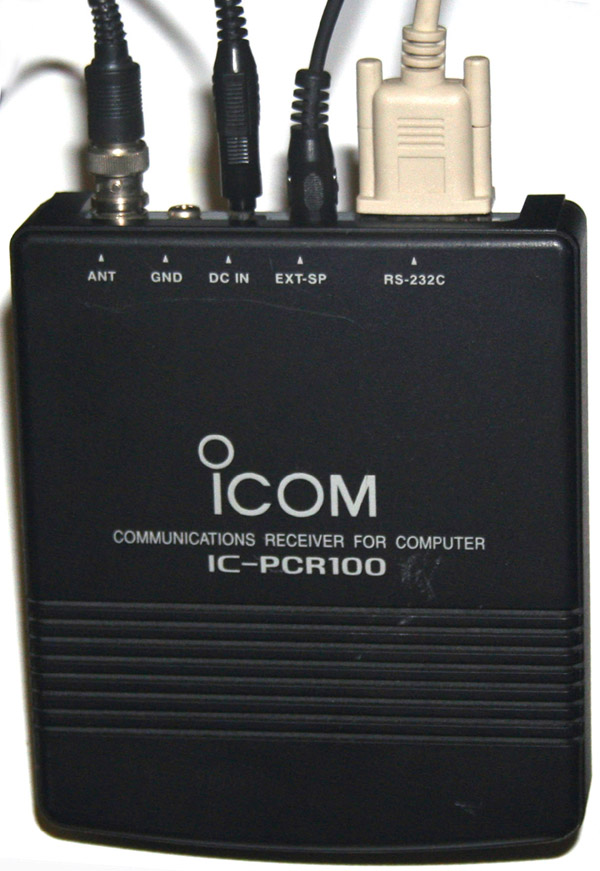
The physical unit measures only 5.2(w) x 1.4(h) x 6.1(d), and is a simple
black box, which may be put out of sight. There are connections for the computer
(rs-232 port), external speakers, power, a 50 ohm antenna, and a ground. The
unit weighs just over a pound. Mine is stuck to the wall behind the computer
which controls it.
Though the radio has fairly good specs, it's
real strength lies in the software written for it. Icom has designed, what
amounts to a software suite for the PCR-100. There are numerous features,
including a built in spectrum analyzer, direct entry or dial tuning, and an
unlimited number of scan frequencies. The frequencies are held in files, which
consist of 20 banks, each containing 50 frequencies. So there are 1000
frequencies in each file. There is no limit to the number of files that can be
created, though only one file may be loaded into the radio control program at a
time. They take the form of text files, and are very small. The radio should,
in theory, never become obsolete, since the newest software will always be
available in the net.
The controls are easily used; buttons are mouse clicked, while dials are
operated using the left and right mouse buttons. It's a pretty intuitive system.
Programming the banks, and frequencies is a simple procedure, and during manual
scan, frequencies found can be easily saved, and put in the appropriate bank.
Frequencies, and banks can be named by the user, for latter reference, and there
is even a memo feature, for entering more extensive information. There are also
controls for the various filters, and noise limiters, along with mode, and scan
controls. A really great feature of this radio is that you can tune it like an
ordinary radio, and are not limited to merely programming scan channels, and
then scanning.
There are a number of hobbyists, and third party software authors, who
write additional programs for the PCR-100. This is perhaps the greatest
advantage of the computer controlled unit. Software is available to decode FSK,
RTTY, weather, fax, and digital communication. There are also programs available
for logging, and for remote operation of the unit over the Internet. Another
nice feature is the flexibility of the frequency files. Once frequencies are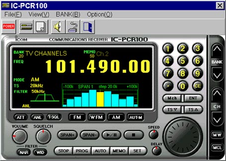 entered, or found and saved during a scan, the frequency files can be copied
and saved, or even traded with other users. There are web sites which have
frequency files, which may be downloaded, and then imported. This is a far
faster process, than consulting a frequency book, and hand entering the
frequencies. Frequencies may be easily updated, over the net, and may be
downloaded for areas or services all over the world.
entered, or found and saved during a scan, the frequency files can be copied
and saved, or even traded with other users. There are web sites which have
frequency files, which may be downloaded, and then imported. This is a far
faster process, than consulting a frequency book, and hand entering the
frequencies. Frequencies may be easily updated, over the net, and may be
downloaded for areas or services all over the world.
Hook up of the radio, is uncomplicated. The unit is plugged into it's
power adapter, the antenna is connected, the 9 pin RS-232 cable is hooked up,
and the speakers are attached (or the unit is plugged into the Line In jack of
the sound card). A special antenna is not required, and I initially used a
simple 20 foot wire, which is included with the radio. Certainly, performance
has been much improved with a proper antenna system; but the wire is good enough
to get you started. Once the physical installation has been made, the software
must be configured. This is a simple matter of selecting the COM port, and
entering frequencies. Please note that this radio was designed in the mid 90's,
and requires a traditional com port. It can not be operated off of a USB port. The impatient user, may wish to skip the frequency
programming, and simply start to scan, or to manually tune the bands. Operation
is seamless, with no band switching required. The frequency steps may be set
from 1khz to 1mhz, and can even cover some of the odd stepping done by the
military.
I presently have this radio hooked up to Porky the computer, and have the following banks set up:
- CB- All forty channels (Why not?)
- Marine- all U.S. and international marine VHF frequencies.
- Police- The local police, along with the sheriff, and fire department
- 2 meter- Mostly local repeater frequencies, though there are a few high traffic areas here also.
- News (SW)- Assorted news and information station on the shortwave bands (Yes, this radio can scan shortwave bands too)
- Air and commercial (Not really many channels in this bank)
As a police, and PS band radio, this is all the radio that anyone could want. The unit receives on AM, and has a discriminator for decoding FM; but no BFO. Thus the only feature that is lacking, to make this the ultimate shortwave, is the ability to receive sidebands. This feature is included on the PCR-1000, but as I have a short wave transceiver, with full receive on the shortwave bands, I didn't figure I needed this ability on my scanner.
Band Scope
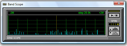 The PCR-100 has a feature in its HW/SW package that it calls a band
scope. This is a sort of a spectrum analyzer lite, and is capable of
sweeping an area of about 2 MHz on either side of the selected frequency.
Signals appear as bars, rising and falling according to signal strength. One
very nice feature of the band scope is that clicking on a signal will shift
if to the center frequency for monitoring. One drawback of the program is
that the center frequency is muted, while the band scope is in operation.
One great use of the band scope is to locate local frequencies and store
them in the unit’s memory.
The PCR-100 has a feature in its HW/SW package that it calls a band
scope. This is a sort of a spectrum analyzer lite, and is capable of
sweeping an area of about 2 MHz on either side of the selected frequency.
Signals appear as bars, rising and falling according to signal strength. One
very nice feature of the band scope is that clicking on a signal will shift
if to the center frequency for monitoring. One drawback of the program is
that the center frequency is muted, while the band scope is in operation.
One great use of the band scope is to locate local frequencies and store
them in the unit’s memory.
The band scope is shown here at its maximum scan width of 4 MHz. Scan width is set by the up and down arrows to the right of the window. Minimum width is 100 KHz. This display can be brought up by clicking on the MENU selection on the Simple-Function Receiver display. The scope is started by clicking on the play/pause control, just above the up and down arrows. Once the scope is started it will continue to run, as a small window just beneath the frequency read out on the Multi-Function Receiver display. The yellow line at the center is the center frequency. The blue spikes all over the screen are signals detected at various frequencies on either side of the center. The height of the blue spikes indicates the signal strength.
A spectrum analyzer is a way to get an overview of what is going on
in a particular band, or a particular portion of a band. It is a graphic
display of a slice of the radio spectrum. Generally, a true spectrum
analyzer will be able to cover an entire band, rather than just a small
slice, and will have some more elaborate ways of processing and displaying
transmission information. I have included some information about true
spectrum analyzer programs that will work with this radio, in a latter
section
Setting up banks and channels
Though the radio can be
manually tuned like an old fashioned SW radio, this unit was mainly designed
to scan frequencies by computer control.
Frequencies may be set manually by typing them in at the computer keyboard,
entering them on the key pad of the virtual radio display using the mouse,
or by simply using the mouse to spin the big virtual radio dial. Putting the
mouse on the big radio dial, and clicking the right button takes the
frequencies up, while clicking the left mouse button takes them down.
Tuning steps are set by using the TS up and TS down keys, which are located
in the virtual radio panel, just below the Mch and ENT keys. Steps can be
set from 1 KHz, to 10 MHz, and are the same steps used by the band scope and
by the auto scan feature. The receiver can also be set for narrow or wide
reception, and there are several filters that can be engaged. Other features
are an ANL, and an attenuator for strong signals.
The main purpose of this receiver was to be used as a scanner, for
UHF/VHF and some higher frequencies. The lower bands were initially
considered as a kind of a bonus. As such, the way in which the scanning
channels and banks are configured is of primary importance. As the radio
itself has no memory and no scanning features, all of this is up to the
software suite included. Though there are now many programs that can operate
this radio, I will concern myself here with the package included with the
radio.
The number of banks and channels is purely a function of the
software. The standard software included provides for 20 banks of 50
frequencies each. These can be set up several different ways.
Hooking up a signal interface
The day will come, particularly
with all of the digital modes used in HF/SW, and the trunking common on
VHF/UHF, when you will wish to use a signal interface to attach your radio
to your computer. A signal interface can be as simple as running an eighth
inch connector from the output of your radio to the input of your computer
sound card; but usually it is not. The receiver operator has a bit of an
advantage over the transceiver operator in this. Where the transceiver
operator may need a somewhat elaborate way of getting receiver and
microphone systems connected between radio and computer, the SW listener
only has to get the receiver signal in. For the PCR-100, this is even
easier, since the radio is already designed for computer control.
What the signal interface does, is
bring the received signal of your radio into your computer for processing.
Ham operators have been doing such things for decades, starting with
computer programs that would decode CW to a screen display, and encode CW from the computer
keyboard. From this, they moved on to FSK, PSK, and packet (a sort of an
Internet over the air waves). There are now also computer programs to
encode/decode pre digital modes, such as SSTV, fax, and even FSTV. Then
there is trunking.
Trunking is the use of a range of
(usually) VHF/UHF frequencies to more efficiently spread communications out
over a given service. A trunking controller will act much as a router acts
in a computer network, with each individual radio being treated as a network
node or workstation. Trunked radios use channels; but these channels are not
frequency selectors, rather, they are talk group selectors. A control
channel, that is monitored by all units, will direct all users on particular
channels to whatever frequency is being used by that group at the moment.
These frequencies are changed according to traffic load. Radio users, on a
trunking system do not select frequencies and have no way of knowing what
frequency they may be using at any particular time. Though not intended as
an encryption technique, to a radio not equipped for trunking, it is nearly
impossible to follow trunked transmissions.
All of the above transmissions
can be accessed by this radio, provided that access to the sidebands is not
required, if a signal interface is used. The best way
to get a good FM signal out of this radio, for use by a computer, is by tapping
the discriminator. The discriminator is the source of the raw received
FM signal, before it is altered by amplification and filtering for listening. This is the
purest, and least distorted form of the received signal. It is also at line
levels and not affected by the volume control. The other advantage of the
discriminator tap is that it allows you to hook your radio up to a computer,
and still retain the use of your radio speaker. For certain features, like
the use of trunking programs, tapping the discriminator is required. Once
this is done, an audio cable may be run from the discriminator tap, to a
sound card line input. Trying the same trick from the regular external
speaker jack in the radio will be very frustrating, and will work poorly if
at all.
Tapping the Discriminator
Tapping the discriminator will
require that you open your radio, partially disassemble it, and then solder
a wire to a plug, and to your circuit board. This can be a bit intimidating,
to the casual radio hobbyist; but it is not that difficult. Before starting,
you will need to have a soldering iron, a screwdriver, a desoldering braid,
12" of fine wire, a drill, and a 3.5mm (eighth inch) jack. One thing that
should be noted is that the discriminator is for FM mode only. This should
not be an issue, as digital modes tend to be used on FM at the higher
frequencies, with AM usually
being too noisy.
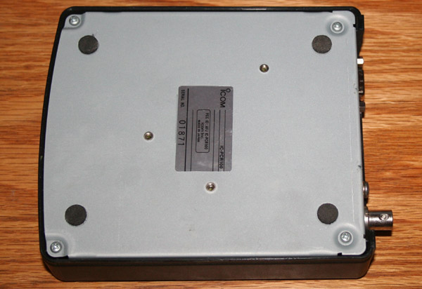 |
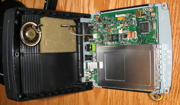
On the bottom of the unit are four screws which hold the cover on. remove these screws, and carefully rock the cover back. Unplugging the small speaker wire will permit the cover to be removed and set aside. You will also need to remove the internal RF shield (the flat piece of sheet metal) to access the board. |
 |
Most instructions that I have seen will now tell
you to remove the seven screws that hold the board down. Some will
advise you to unscrew the collar that holds the antenna plug, while
others will instruct you to desolder the plug from the board. The
board is then to be turned over, IC-10 is to be located, and a
resister soldered to the via pad by pin 8 of IC-10. You are welcome
to try either method. Instructions for doing it this way are at http://members.cox.net/fiftyone.50/TrunkPcr/pcr100mod/pcr100.html http://tinker.fulhack.info/content/pcr100 |
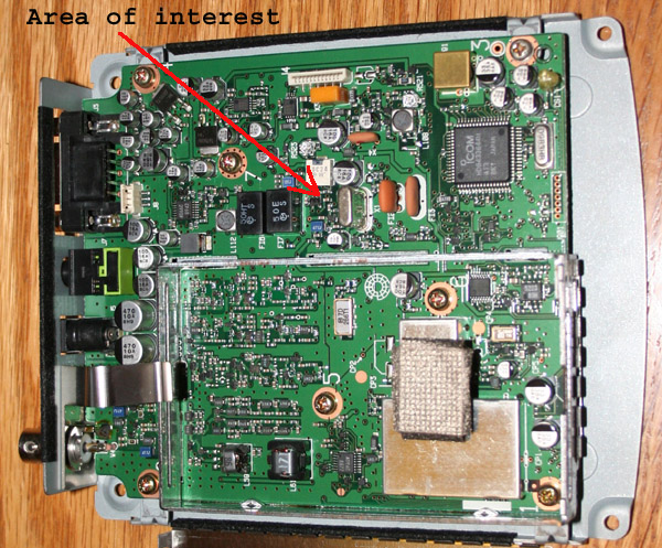 |
I tried it a different way. Being basically lazy, I didn't want to desolder everything. Being basically paranoid, I didn't want to chance foil separation on the PC board, when removing it from the unit. I also do not have the little tool required to remove the BNC connector collar, and did not wish to screw around with pliers and such, mangling the case and possibly the collar. So I traced where the other side of the pad would come up on the top of the board. it is approximately half way up, on the unshielded side of the board. |
e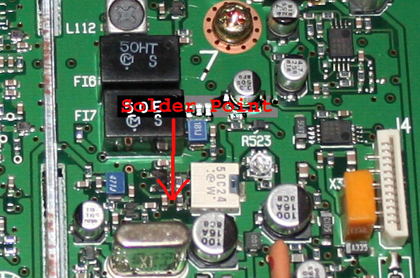 |
The arrow points to the other side of the pad by pin 8 of IC-10. it is a pretty tight squeeze between those surface mount components. This photo is rotated 90 degrees from the one above. |
| I painted the pad with flux, before tinning and then twisting the wire into the opening. It seems to be in there for good. I then ran the wire up the side of the shield, and soldered it to the 10k resister. This was then soldered to the center connector of the 3.5mm jack. The outside connector was soldered to ground. |
There is a considerable amount of third party software that can be used on this radio. Most is general purpose, like PSK, fax, and RTTY software, while some is model specific. As the PCR-100 has been discontinued for several years, there is little new software being written for it. Most of the older software is still available, and software is still being written for its big brother, the PCR-1000. PCR-1000 software will work on the PCR-100, as the command sets for the two radios are the same. This includes the driver and operating program written by Icom.
In most ways, the PCR-1000 software is better, except for the odd fact that the bandscope will only go up to 200 KHz, rather then the 2 MHz of that for the PCR-100. Still, there are some interesting features, and a flexibility in the PCR-1000 software that the PCR-100 software does not have. I would recommend getting both packages, and using the one that you prefer.
The current heir apparent is the PCR1500 – PCR2500 series of PC radios. It appears that the software suite is not dissimilar to that of the PCR-1000; but it can not be made to work with the PCR-100, mainly because it searches the USB port for comm. It may be that it could be made to work, by using a USB to RS-232 adapter; but I see little point, as it appears to offer no new features over those in the PCR-1000 package.
Subjects I will cover when I get time, and
learn more:
trunking
spectrum analyzer
waterfall
DSP
fax
fsk
PSK
packet
recording
 Most scanners and short wave radios have horrible little whip antennas, or
internal bar antennas made from wire wrapped ferrite bars.
Most scanners and short wave radios have horrible little whip antennas, or
internal bar antennas made from wire wrapped ferrite bars.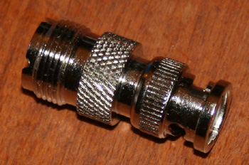 These antennas capture little signal, and are often not even close to being
resonant on the required frequencies. Some of the better radios will have
connectors for an external antenna. On a SW radio, this will usually be a pair of screw leads for a
wire dipole, or other balanced line. On a VHF/UHF scanner, this will
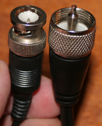
generally be a BNC connector. The choice of a BNC connector seems
rather strange, since there are few antennas, outside of the rubber duck
types, which use it. The most common antenna connector is the PL-239, shown
in the photo to the left, which sits on the end of most 50 ohm unbalanced
coax. The photo also shows the smaller BNC connector. This is the type of
connector located on the panel of the PCR-100. In order to connect to an
antenna, I needed an adapter, like the one show above and to the right.
These antennas capture little signal, and are often not even close to being
resonant on the required frequencies. Some of the better radios will have
connectors for an external antenna. On a SW radio, this will usually be a pair of screw leads for a
wire dipole, or other balanced line. On a VHF/UHF scanner, this will
generally be a BNC connector. The choice of a BNC connector seems
rather strange, since there are few antennas, outside of the rubber duck
types, which use it. The most common antenna connector is the PL-239, shown
in the photo to the left, which sits on the end of most 50 ohm unbalanced
coax. The photo also shows the smaller BNC connector. This is the type of
connector located on the panel of the PCR-100. In order to connect to an
antenna, I needed an adapter, like the one show above and to the right.
For this extremely broad banded scanner, there really is only one antenna choice. For decades, scanner owners have been enamored of the discone antenna, and for a number of good reasons. As the name implies, the antenna consists of a disc centered on top of a cone, making it look like something out of a science fiction movie. It is fed by a 50 ohm coax, with the center conductor going to the disc, and the braided outer conductor going to the cone.
A discone is unique in that it has a very wide bandwidth. It’s main resonance is set by adjusting the diameter of the disc and the cone. The disc of the antenna is 0.17 of the wavelength of the resonant frequency desired, or about 0.68 of a quarter wave. The cone is a quarter wave long, and is designed at a 30 degree angle to give it a base which is a quarter wave in diameter. The cone and disc are kept separate by an insulating spacer. The space is generally 0.10 of an inch, presuming that the diameter of the open top of the cone (through which the coax must pass) has a diameter of 0.5. of an inch – these two measurements must be proportional. Experimenters will sometimes try various spacings of the disc and cone, as well as different cone angles, to see how these might affect bandwidth, and swr.
 The original discone design used a solid sheet metal disc, on top of
a solid sheet metal cone. They can still be made this way, and this is
probably the most efficient form of this antenna; but usually construction
consists of a number of radials emulating the discone shape. This is
particularly true of larger antennas designed to operate on lower
frequencies. The traditional arrangement is of sixteen radials for the disc
and another sixteen for the cone. The number of radials can be reduced; but
this causes the SWR to go up, and the bandwidth to go down. The further you
get from a solid surface, the less efficient the antenna will be.
The original discone design used a solid sheet metal disc, on top of
a solid sheet metal cone. They can still be made this way, and this is
probably the most efficient form of this antenna; but usually construction
consists of a number of radials emulating the discone shape. This is
particularly true of larger antennas designed to operate on lower
frequencies. The traditional arrangement is of sixteen radials for the disc
and another sixteen for the cone. The number of radials can be reduced; but
this causes the SWR to go up, and the bandwidth to go down. The further you
get from a solid surface, the less efficient the antenna will be.
Unlike standard antennas, where the resonant frequency should be centered on the desired band, a discone needs its resonant frequency set to the lowest value that you plan to use. Where a normal antenna has radiation, and thus efficiency, gradually taper off on both ends of the resonant frequency, the discone tapers off very slowly as frequency rises, but very quickly as frequency gets lower. This makes the discone almost useless on frequencies below its resonance, though it has a very high bandwidth for frequencies above resonance. Antenna makers advertise 10:1 bandwidths; but this is a bit of an exaggeration. Some manufacturers have made claims of a useful range of 25MHz to 1300 MHz, for antennas with cones of 32”. Though they are correct in that SWR will remain low across such a bandwidth, from about 100MHz through 1300MHz, efficiency will drop after about a 3:1 bandwidth has been reached.
The discone would seem to be ideal, nearly the perfect antenna; but it does have a few problems, when compared to more conventional antennas. The most obvious issue, is it’s great size and weight. This is one of the reasons that when you see a discone, it will almost always be for use on VHF/UHF frequencies. Discones for lower frequencies would be way too big and heavy.
Though it would be possible to build a CB or HF antenna on the
discone pattern, the disc would be an eight foot circle of copper or
aluminum. Just for laughs, an HF antenna designed for 160 meters would have
a disc of 120 feet, and a height of around 130 feet. This would make it
larger and heavier than most apartment buildings. The neighbors would think
that a space ship just landed, and we were being invaded by Martians. I suppose I could build
one, and then move in with my furniture, and perhaps put in plumbing. I am
not so certain about electricity, as it might wreak havoc with the radiation
pattern. The largest discone that I have actually seen, is at the
The other issue with the discone is that it produces no gain. This is particularly notable because of the great size of the antenna. This is despite a rather low angle of radiation within its usable range. This low angle of radiation also makes it important to orient the antenna properly. At usable frequencies, this is a full Omni-directional antenna with the pattern perpendicular to the cone, and extending out from the disc like a flattened donut. Unfortunately, as with any antenna, the pattern changes as the frequency changes. This is why I use multiple discones.
Many discone owners complain about performance on the higher frequencies. Some owners of the Diamond discone have even complained that their little rubber duck antennas have performed better on 800MHz than the big 32" discone. They are both right and wrong. A discone antenna of this size still shows good SWR and good sensitivity at 800MHz; but its pattern has changed drastically. Once a frequency of about triple that of the resonance has been reached, lobes start to form. By the time the frequency is five times resonance, around 500 MHz for an antenna of this size, the angle of radiation is about 45 degrees. At 800 MHz, the pattern would be very nearly pointing straight up at the sky. Unless you are listening for 800 MHz transmissions from airplanes, and one happens to be passing through one of your lobes when it transmits, you are not going to hear much. This is not unique to the discone. A dipole, at several wavelengths radiates almost straight out the end.
As a transmitting antenna, the discone is a bit less suitable, though it can be used to transmit, and is equally broadbanded as a transmit antenna. The main problem, besides the lack of gain, is the very broadbandedness of the antenna itself. What this means is that harmonics, as well as primary frequencies may be transmitted.
Even with the versatile discone’s celebrated wide band, more than one antenna is required to cover everything properly. Practical requirements also rule out its use for the SW bands. The following four antennas feed into my scanner:
Discone – 32” cone/23" disc - (40)100 – 300 MHz radials
Discone – 11” cone/7.7" disc – 300 – 900 MHz aluminum sheet
Discone – 5” cone /3.5" disc - 550 – 1650 MHz aluminum sheet
Dipole with fanned elements - 3 - 35 MHz wire
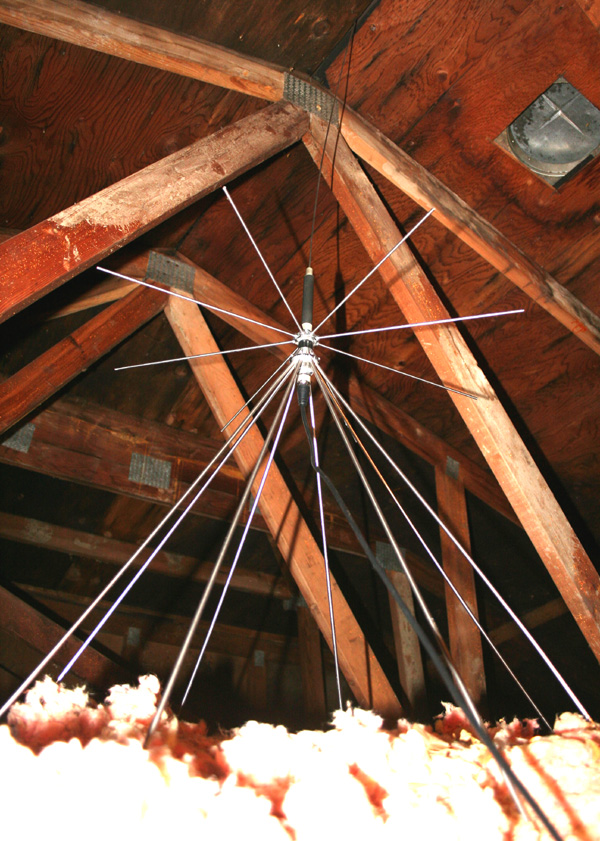
With these four antennas, I can cover everything from less than half a megahertz to 1300 MHz, with a slight drop in efficiency between 60MHz and 88MHz, another slight drop around 35MHz - 40MHz, and a more substantial drop under 3 MHz. I am not deaf at these frequencies; but merely can not hear quite as well. Due to neighborhood restrictions, all of my SW antennas are indoors, in a four foot high attic crawl space.
The Diamond discone is a really high quality unit, well made, and generally considered the best of this class of antenna. Unfortunately, it does not quite cover all of the bands claimed. Measurement of the disc is 26" and that of the cone 32". This gives it a resonance of about 100MHz. Diamond has attempted to remedy this a bit by topping the unit with a base loaded antenna of approximately 50MHz resonance. This gives the antenna limited capabilities on the 6 meter band; but does not address the basic issue that a discone antenna for use on the range of frequencies claimed would need to be twice the size for use on 6 meter, and four times the size to really cover 25MHz. I am not faulting the antenna - it is a great unit; but the claims made for it are unrealistic.
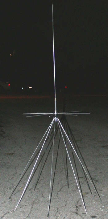
Having leveled my criticisms, I have to say that this antenna does pretty much anything that most scanner operators would wish. It's useful discone coverage begins around the top end of the FM radio bands, and goes up to the 1.25 meter band. Limited coverage is even possible on 440MHz, though it is not an ideal antenna at these frequencies, due to the changing radiation pattern. Unfortunately, the discone resonance of 100MHz means that below 100 MHz, coverage disappears quickly. The photograph to the right was taken at night, to try and emphasize the shape of the antenna by highlighting it with flash. Strictly speaking, the large vertical radiator at the top is not part of the discone, making this a hybrid antenna.
To somewhat make up for this blind spot, Diamond has added a base loaded antenna for 50 MHz. So essentially you are running two antennas off of the same coax: a 100MHz discone, and a 50MHz quarter wave vertical. I don't actually have a huge problem with this. FM radio stations, should I chose to listen to them on my scanner, are powerful enough and near enough, that a really good antenna match would not be required. This leaves a somewhat lossy area between around 60MHz, and 88MHz, which is pretty much covered only by the base loaded vertical. This element does not have the discone bandwidth properties, and will become very inefficient by the time the 100 MHz resonance of the discone elements begins to kick in. Still, this is a pretty small portion of the spectrum, and the vertical element does a good enough job for a receiver.
Where people run into problems with this antenna, is when they attempt to use it to transmit. The discone portion of the antenna is pretty good on 2 meter, and adequate on 440; but above that, most of your energy is going into space. SWR will remain pretty low all across these VHF and UHF bands, even though pattern and efficiency will not be so good. Going to the lower frequencies you will have problems. Though the vertical element of this hybrid design is resonant on 50MHz, it does not really have enough bandwidth to cover the entire 4 MHz range of the 6 meter band as a transmitter antenna. This is largely because the ground provided by the cone portion of the antenna, which at these frequencies acts as a ground plane, does not have a large enough area. A ground plane for this band should be twice the size.
Antennas, like everything else, are a compromise. The discone permits a bit less compromise than more conventional antenna systems. The ideal antenna system would have a separate resonant antenna for each band. This would give good efficiency, and good pattern on every band. For conventional antennas, this would require a large number of separate elements. With the dicsone I can get away with using three, to cover a range that would require dozens of conventional antennas.
Home Brew Discones for VHF/UHF
In order to
keep my pattern low, and my efficiency high, I use a trio of discone
antennas to cover the entire range. The two smaller antennas are home made,
and are quite a bit smaller than the unit from Diamond. These are made of
sheet metal, with the disc cut to size, and the cone cut and bent to size.
The ratios are given above, and are pretty easy to calculate and cut.
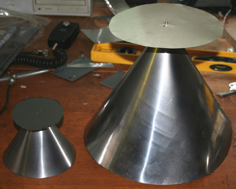 The smaller discones were home made, and pretty easily constructed. They
were made from sheet aluminum, actually from metal ducting designed for use
in home heating and air conditioning. Copper sheet would probably have been
better; but it is much more expensive, and much more difficult to work.
Total cost for both antennas was around $7 for the sheet metal, and then a
few dollars for the connector for the larger antenna and the coax for the
smaller. The disc and cones are cut according to the measurements given
above, and are resonant on the frequencies shown. The three are lined up
right by the trap door of my attic crawl space. They are pretty close to
being directly above my radio, since this makes for a shorter cable run.
Attenuation due to cable loss is quite a bit more marked on the higher
frequencies.
The smaller discones were home made, and pretty easily constructed. They
were made from sheet aluminum, actually from metal ducting designed for use
in home heating and air conditioning. Copper sheet would probably have been
better; but it is much more expensive, and much more difficult to work.
Total cost for both antennas was around $7 for the sheet metal, and then a
few dollars for the connector for the larger antenna and the coax for the
smaller. The disc and cones are cut according to the measurements given
above, and are resonant on the frequencies shown. The three are lined up
right by the trap door of my attic crawl space. They are pretty close to
being directly above my radio, since this makes for a shorter cable run.
Attenuation due to cable loss is quite a bit more marked on the higher
frequencies.
Construction of the two smaller discones was easier than I though it would be. The aluminum sheet used in most ductwork is easy to cut. I laid out the patterns first, measuring my disc, and then the half disc that would become the cone. The aluminum was thin enough and soft enough that I was able to use a pair of scissors to cut the shapes. Though the design gives a fair amount of latitude, I wanted these shapes to be as accurate as possible.
Once the pieces were cut, they needed to be joined, after shaping the cone. Shaping and joining the cone was not as easy as I had thought. The thin sheet aluminum resisted all attempts at soldering it. Even had I gotten a good solder joint, the thin sheets are so flexible it would have been like soldering paper. I resorted to staples and metal tape to form and hold the cones together.
With the larger cone formed, I then cut and spread about an inch of the point of the cone. I used the petals formed to connect and solder the PL-239 connector. Around the top of the connecter, and between the disc and the cone, went some plastic and rubber washers, to act as insulators. These were glued in place. Finally, the disc was set on top, with a hole in the middle to attach the center wire of the PL-239 connector. This type of construction does not make for a very sturdy antenna, and I doubt my homebrews would last a week outside; but for the attic, they are fine, and they work great. They are also cheap.
The smaller cone was just too small to try and install a connector. Instead, I soldered the wires of the braid directly to the cone, and the center wire directly to the disc. I used a small piece of plastic to separate the two, and to hold the antenna together.
An unconventional multi wire dipole for SW/HF
For the SW bands, I take a more traditional approach, though still somewhat unconventional. The multi element wire dipole is the classic antenna of the short wave listener. Unlike the discone, a separate element is nominally needed for every band. Thicker wire provides more bandwidth, and tubing more still. Wire is generally preferred for this type of antenna, due to its ease of use, flexibility, lower cost, and the great length required for antennas operating on the SW bands. This antenna has eight wires, divided up into four two-wire dipoles. All are joined at a single coax cable, connected via BNC to my radio. Though this arrangement might not work so well for transmitting, it is fine for reception.
It might seem that the best solution would be to get an antenna cut to the length of the longest frequency to which you plan on tuning the radio - similar to the set up of a discone. Though a long antenna can be matched on shorter wavelength frequencies, there are some drawbacks. SWR will be high; but this is a minor inconvenience, and can be handled by a tuner; in a pure receiver it can be ignored. What becomes a real problem is that the radiation pattern changes in a not very useful way. From the original donut of the half wave dipole, there develop lobes and nulls. Eventually, at several wavelengths, the signal is beamed straight out the end of the antenna - not very useful. Because of this, many antennas are designed with multiple elements or traps. Traps can be inefficient, and difficult to properly fabricate, so I decided to go with the classic multi element construction.
Though the shortwave bands are mixed in with the HF ham bands, the frequencies are different and thus resonant wire lengths are different. In other words, a ham antenna will not make a good SW antenna, and vice versa. Traditionally, four wire pairs are used, which are resonant on eight SW bands, and somewhat resonant on two more. The reason for this is that a half wave antenna can act as a half wave with a full wave ground on the third harmonic frequency. What this means is that an antenna that is resonant on 90 meters (3.25 MHz) as a half wave will also be resonant on 30 meters (9.75 MHz) as a full and half wave. The usual problems surface here, with the radiation pattern changing. However, these differences are less important on SW transmissions, which usually depend on sky waves to propagate. In addition, in no case, is the wire antenna required to serve for frequencies which would make it three to five times (or more) the wave length of the frequencies being received - which is where the really extreme pattern changes begin. The problem of radiation pattern is thus not really an issue with this antenna on the SW bands. The resonant lengths on the SW bands are in the table below:
|
Wire |
Resonance |
3rd
Harmonic |
Length |
|
1 |
3.25 MHz (90 meter) |
09.75 MHz (31 meter) |
468 ÷ 3.25 = 144' 0" |
|
2 |
3.95 MHz (75 meter) |
11.85 MHz (25 meter) |
468 ÷ 3.95 = 118' 6" |
|
3 |
5.10 MHz (60 meter) |
15.30 MHz (19 meter) |
468 ÷ 5.10 = 91' 9" |
|
4 |
5.90 MHz (49 meter) |
17.70 MHz (16 meter) |
468 ÷ 5.90 = 79' 3" |
Typically, the four dipole wire antenna is made by cutting four sets of wire to the appropriate lengths, and then connecting them all together at the coax. So how does the radio "know" which antenna pair to use? The selectivity of the receiver takes care of this. When a given frequency of radio wave crosses the elements of the antenna, only the resonant element really absorbs the energy. The other elements barely notice. So the signal will be so much stronger from the resonant element that any signal emanating from any of the other elements will simply be overpowered.
This particular antenna is based upon one of the many variations of the Slinky antenna available. The original Slinky element is used as the longest element. In addition, the original balun is used. Some changes were required, due to the original design parameter of the Slinky. Many years ago, ham operators discovered that, coincidentally, the 65'-67' length of the wire coil of the Slinky made it approximately a quarter wave at 80 meters. Thus two Slinkys could be used to make a rather short 80 meter dipole. One of the great advantages of this is that this makes the antenna tunable, via suitable matcher, on most of the ham bands excluding the longer 160 meter band. Thus a number of antenna makers offered Slinky antennas.
The basic construction of the antenna is just like that of the traditional multi element wire dipole, except that Slinkys are cut to resonant frequencies, and used instead of wire. These are then soldered to the balun connection. Each slinky element is supported by a line anchored to the ends of my attic crawl space. In case you are wondering why I bother to go through the trouble, it is because I was not looking forward to stringing over 400 feet of wire around my 30' x 35' attic crawl space.
- Frequency Coverage: 0.010 - 1300.000 MHz*
- *Specifications guaranteed 0.5 - 1300 MHz only. Cellular blocked on USA versions: 824 - 849 MHz, 869 - 894 MHz
- Mode: WFM, FM, AM
- Number of Memory Channels: 1000 channels per file (50 channels x 20 banks, number of files created is up to the user)
- Tuning Steps: 1, 5, 6.25, 9, 10, 12.5, 15, 20, 25, 30, 50, 100, 500 kHz and 1 MHz
- Useable Temperature range: 0° C to +50° C; 32° F to 122° F
- Frequency Stability: ±5ppm (0° C to +50°, at 1300 MHz)
- Power Supply Requirement (negative ground): 13.8 V DC = ±15% or specified AC adapter
- Current Drain:
- PC Off 100 mA
- Standby (squelched): 600 mA
- Max. Audio: 700 mA
- Receive System: Triple conversion superheterodyne (except WFM)
- Intermediate Frequencies:
- 1st -- 266.7 MHz
- 2nd -- 10.7 MHz
- 3rd -- 450 kHz (except WFM)
- FM/AM -- 6 kHz/-6 dB, 15 kHz/-6 dB
- WFM/FM/AM -- 50 kHz/-6 db
- WFM -- 230 kHz/-6 dB
Software
|
This receiver is no longer
manufactured or supported. If you have lost your set up discs, I have zip
files of the two floppies at the links below. I have had good luck installing
these in compatibility mode, though some suggest copying over part of
the PCR-1000 software package to insure compatibility. The problem is
with the file "rxbase.dll". The solution usually given is to download
the PCR-1000 install software, and copy "rxbase.dll" into the directory
into which the PCR-100 software has been installed. Please note that I
have not had to do this, and I have had no difficulty running this
program in Windows 95 compatibility mode. If you are not familiar with setting up a program to run in Compatibility Mode, the process is not difficult, and is certainly easier than installing two software packages, copying a file over, and then removing the un-needed software. The process is as follows: 1 - Install the program in the normal manner. 2 - Once the program is installed, right click on it's icon, which should produce a drop down menu. 3 - At the bottom of the drop down menu, select and click on Properties. 4 - In the properties box that now comes up, click on the tab that says Compatibility. 5 - Put a check mark in the box that says "Run this program in compatibility mode for:" 6 - Just below the check mark will be a menu with an arrow - click on the arrow to display all menu selections, and click on the Windows 95 selection. 7 - Click on Apply or OK to save this change. |
|
| Floppy 1 | Floppy 2 |