The Kenwood TS-811
Multimode 70cm transceiver
| Manual | The 70 cm band | Factory Specifications | Computer Interfacing |
| Modifications | Converting the D to A | Antenna | Links |
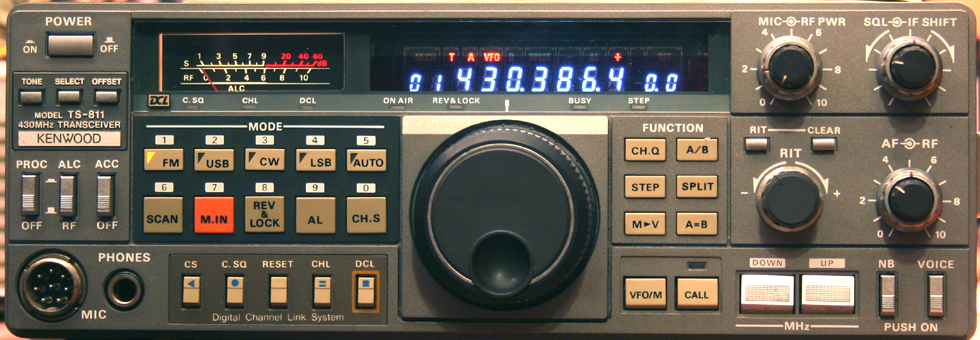
The Kenwood TS-811 is, more or less, the 70cm twin of my TS-711. Both are styled after the TS-440. The features are similar, and the styling is identical. These units were all introduced at about the same time, mid to late eighties, and even use some of the same accessories (such as the computer interface). Unlike the HF model, the UHF versions have a built in power supply, and can be plugged directly into the wall. This is an all mode transceiver, and is not limited to FM like most 70cm units. This was Kenwood's middle range series. Though there were some initial issues, due to this being the rather rare (and frequency limited) Japanese units, once I made some modifications, I found myself with what I consider to be the ultimate 440 base.
Inside, the radio looks nearly identical to my TS-711A.
Both radios take the same accessories, and have identical
operating procedures. In both cases, these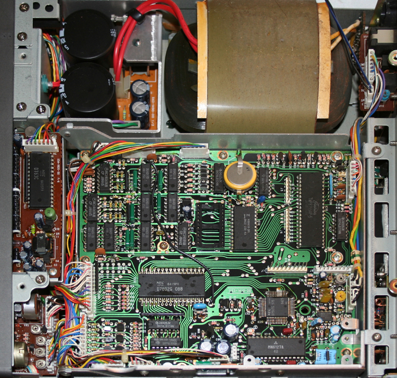 are 13.8 volt radios, with built in
transformers that come out and then plug back into the
radio. This is why the rear Molex plug must always be
inserted when operating off of house current. As can be
seen from the photograph, the radio was without the tone
board, speech board, and computer interface. The tone
board would have been installed in the right rear corner
of the board, which is the lower right hand side of the
photo. The speech board would have gone next to it, and
the computer interface board would have installed near the
center of the board, by the empty IC socket.
Adding all of these boards, with the possible exception of
the speech board, will make this a $600 radio - one of my
more expensive units.
are 13.8 volt radios, with built in
transformers that come out and then plug back into the
radio. This is why the rear Molex plug must always be
inserted when operating off of house current. As can be
seen from the photograph, the radio was without the tone
board, speech board, and computer interface. The tone
board would have been installed in the right rear corner
of the board, which is the lower right hand side of the
photo. The speech board would have gone next to it, and
the computer interface board would have installed near the
center of the board, by the empty IC socket.
Adding all of these boards, with the possible exception of
the speech board, will make this a $600 radio - one of my
more expensive units.
This has been a long awaited and anticipated addition to my shack. The TS-811 is one of the very few all mode 440 (70 cm) radios. It is desk sized, makes a great base, and is very satisfying to operate. Most 440 users operate off of hand helds, or perhaps a mobile with a DC power supply. These are normally set up to transmit on 430 – 450 MHz. The Canadian version only goes up to 440 MHz, as do the European versions. Though the band goes down to 430 MHz, most of these radios will not transmit down this far. This is by design; the portion of the band between 420 and 430 is generally used for amateur TV transmission.
My radio is not an American version, which is probably a good place to explain about the model variants on the Kenwood mono-band 811/711 radios. These radios came in A, B, D, and E versions. There is no C model of which I am aware. The variants are essentially the same radio, with different diodes, jumpers, and programming. To a certain extent, mods can convert one type to another, though it is more difficult with some models. A summary of the differences is below:
-
TS-811A American version - 430 - 450 MHz, 25 watts, PL tones (option), 5 MHz split as well as custom split. 110 - 120 VAC.
-
TS-811B No information. (If anyone has any info, I would appreciate hearing from you)
-
TS-811D Asian version - 430 - 440 MHz, 25 watts, PL tones (option), DCS tones, 5 MHz split as well as custom split 100 VAC.
-
TS-811E European version - 432 - 438 MHz, 25 watts, Tone Burst, 1.6 MHz split as well as custom split 240 VAC.
Some versions of this radio only put out 15 watts. This particular unit puts out 25 watts. This is enough power for local communications, within the limitations of this band. It is also enough power to run a good quality linear amplifier up to full rated power. There are few 70 cm bases made - I am unaware of any in current production. There are also very few SSB/CW radios made for this band. I initially purchased this radio, out of curiosity, and because the price was right. I also wanted to get the third member of the old Kenwood trio.
Most users of 70 cm are doing satellite, amateur
television, or talk on small handhelds through local
repeaters. There is some mobile use, generally through
dual band units; but the frequencies are not much used for
base operations. So who can I talk to on this rig? Well,
the answer is not much of anyone. We do have a few
repeaters around, but even on the repeaters I do not often
find much traffic. Having a good antenna, high off the
ground, has helped; but most repeater users are on the 2
meter band, and consider 70 cm as a secondary.
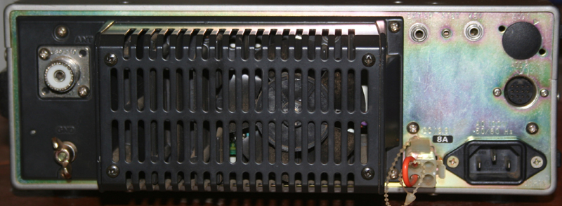 Though this is of the same series as the TS-440,
and shares that unit's all mode operation, the TS-811 is a
bit less capable,
being more of a twin of the more popular 2 meter 711. Like
the 711, it
is missing many of the connections, which give the HF unit
so much of it's
flexibility. The rear panel features an antenna connector,
ground, power
connectors for 120v and 13.8 volt, computer interface, and
audio jacks.
Most activity, on the 70cm band, is FM, making it hard for
many ham operators
to justify the expense of an all mode radio.
Though this is of the same series as the TS-440,
and shares that unit's all mode operation, the TS-811 is a
bit less capable,
being more of a twin of the more popular 2 meter 711. Like
the 711, it
is missing many of the connections, which give the HF unit
so much of it's
flexibility. The rear panel features an antenna connector,
ground, power
connectors for 120v and 13.8 volt, computer interface, and
audio jacks.
Most activity, on the 70cm band, is FM, making it hard for
many ham operators
to justify the expense of an all mode radio.
Installing the IF-10A (more on this latter) permits computer control. The accessory plug permits direct data connection, in and out, to the radio. These two connectors permit complete computer control and connection. The command set is a bit limited, due to the technology of the time, but it is still enough to do amazing things with this radio.
One interesting thing
to consider about 70 cm is that its bandwidth of 30 MHz is
a bit larger than that of the entire HF spectrum. Even
more striking is that if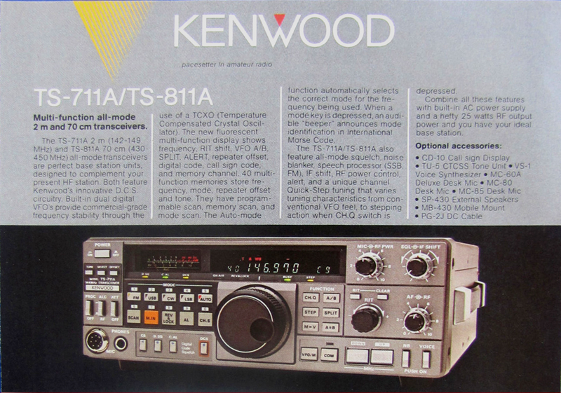 you add
up all the frequencies allocated to amateurs in the HF
spectrum, they come out to only 2.85 MHz. This gives those
of us who operate on 70 cm a lot of room to play.
Admittedly, due to the characteristics of these
frequencies, you can not work DX or talk to the world on
UHF; but a 30 MHz bandwidth offers many possibilities.
you add
up all the frequencies allocated to amateurs in the HF
spectrum, they come out to only 2.85 MHz. This gives those
of us who operate on 70 cm a lot of room to play.
Admittedly, due to the characteristics of these
frequencies, you can not work DX or talk to the world on
UHF; but a 30 MHz bandwidth offers many possibilities.
Most hams consider this to be THE UHF band, though there are others. Sadly, there was a possibility of losing a big chunk of this band to unspecified medical devices. The FCC was considering auctioning parts of the band off. This is no longer a concern, as of this writing; but once the government gets an idea, vigilance is the watchword. In Europe, the band was iinitially only a 10 MHz sliver (430 - 440); but even this was reduced. The politicians that run the allegedly united Europe have whittled it down to 432 - 438.
In the United States, we have full use of the full spectrum, though this can vary in certain locations. There are certain areas where portions of the band can not be used due to interference with some types of radar. Also, out of respect to our Canadian neighbors, a line running south of Canada, and also across a portion of Alaska, denotes the boundaries of the use of the 420 MHz to 430 MHz portion of the band, so that transmissions do not interfere with Canadian PS radio services. As a general rule, where they are permitted, frequencies below 430 MHz are used for amateur television, which is why even the American version of this radio does not transmit below 430. For TV, a special transmitter is used, which operates on a much wider bandwidth. A general band plan is listed below. The band plan has no legal weight, but is largely held to by most amateurs.
420.00-426.00 ATV repeater or simplex with 421.25 MHz
video carrier control links and experimental
426.00-432.00 ATV simplex with 427.250 MHz video
carrier frequency
432.00-432.07 EME (Earth-Moon-Earth)
432.07-432.08 Propagation beacons (old band plan)
432.08-432.10 Weak-signal CW
432.100 UPPER SIDE BAND 70 cm calling frequency
432.10-433.00 Mixed-mode and weak-signal work
432.30-432.40 New beacon band
433.00-435.00 Auxiliary/repeater links
435.00-438.00 Satellite only (internationally)
438.00-444.00 ATV repeater input with 439.250 MHz
video carrier frequency and repeater links
442.00-445.00 Repeater inputs and outputs (local
option)
445.00-447.00 Shared by auxiliary and control links,
repeaters and simplex (local option); 446.00 MHz
national simplex frequency
447.00-450.00 Repeater inputs and outputs

As a UHF band, 70 cm is largely limited to line of sight. This translates to range being directly related to antenna height. Increasing power can sometimes overcome obstacles of local noise, and penetration through foliage or other obstacles; but does nothing to increase range. As with everything in science, technology, and radio, there are exceptions. The 70 cm band can get long range through atmospheric ducting, meteor showers, and the working of repeater satellites. These are challenging pursuits, and have become hobbies in their own right.
Under normal point to point communication, 70 cm has slightly reduced range over that of 2 meter, though again circumstances can affect this. The 70 cm range is said by some to have better building penetration, and be better suited for urban areas, but this depends upon the building. Higher frequency radio can be more easily blocked, but can also more easily penetrate smaller openings. A part of the 70 cm band is very close to the FRS/GMRS band. Though more power is allowed, propagation is similar. As with GMRS, range between hand held radios is a mile or so. Range between mobiles may be as much as five to seven miles, and range between bases can be as much as twenty to thirty miles. These ranges are all subject to conditions, and can be far greater if one or both stations are located at high elevations.
One significant advantage that 70 cm has over 2 meters is in the area of antennas. Where a quarter wave antenna for 2 meters would be 18" long, the same type of antenna for a 70 cm would be about 6". This gives a large advantage to 70 cm for handheld operation. There is a practical limit to how long an antenna mounted on a portable can be. A six inch antenna mounted on a hand held radio will be a quarter wave long on 70 cm, giving a potential efficiency of 22%. The same antenna used for two meter would be roughly a tenth of a wave, giving a possible efficiency of perhaps 1.5%. Even though the antenna can be made electrically a quarter wave on two meter, the actual physical length determines its potential efficiency.
The relatively small antennas required by this band is one of the reasons that its use is so popular for satellite work. Hitting a satellite a couple hundred miles up requires a very high gain antenna. Typically, a Yagi style antenna is used, having anywhere from three to seven (or more) elements on a boom that could be anywhere from 18" to over three feet long. Most satellites are cross band repeaters, transmitting on one band, and receiving on another.
One use to which the frequency range of 70 cm lends itself is amateur television. A regular fast scan television signal requires a bandwidth of about 4 - 6 MHz. Fast scan television is not possible on any of the lower bands, due to limited bandwidth. The entire two meter band would barely be able to hold one fast scan transmission. Fast scan television requires special transmitters, which are broadbanded. The TS-811 can not do fast scan television. A regular voice transmitter/transceiver will put out a signal width from 12.5 KHz to 25 KHz - far too narrow for fast scan television. Previously, hams who wanted to send pictures could do slow scan television, still used on the lower frequency bands. Slow scan is more like a slide show than a real television transmission, but can be sent using a regular transmitter, and requires no more signal width than a voice transmission.
| Modes | LSB (A3J), USB (A3J), CW (A1), AM (A3), FM (F3), FSK (F1) | ||
| Antenna Impedance | 50 Ohms | ||
| Grounding | Negative | ||
| Power Requirements | 120v / 13.8v | ||
| Current Drain | Receive Mode with no input | 50 Watts | |
| Transmit Mode | 220 Watts | ||
| Operating temperature | -10 to +50 C (+14 to +122 F) | ||
| Dimensions | Wide
High Deep |
10.6 Inches 3.78 Inches 10.2 Inches |
|
| Weight | 15.6 pounds | ||
|
|
|||
| Frequency range | 430 MHz - 440 MHz (Japanese version)/430 MHz - 450 MHz (American) | ||
| Input Power | LSB, USB, CW, FM, FSK | 25 watts | |
| AM | 25 watts | ||
| Modulation | LSB, USB | Balanced Modulation | |
| FM | Reactance Modulation | ||
| AM | Low Level Modulation | ||
| Spurious radiation (CW) | Less Than -40 db | ||
| Carrier Suppression | More Than 40 db (With 1.5 KHZ Reference) | ||
| Unwanted Sideband Suppression | More Than 50 db (With 1.5 KHZ Reference) | ||
| Third Order Distortion | More than 26 db below one of two tones | ||
| Maximum Frequency Deviation (FM) | 5 KHZ | ||
| Frequency Response (-6 db) | 400 to 2600 HZ | ||
| Microphone Impedance | 500 Ohms to 50k | ||
|
|
|||
| Circuitry | Triple Conversion Superheterodyne | ||
| Frequency range | 430 MHz - 440 MHz (Japanese version)/430 MHz - 450 MHz (American) | ||
| Intermediate Frequency | 1st: 45.05 MHZ, 2nd: 8.83 MHZ, 3rd: 455 KHZ | ||
| Sensitivity | LSB, USB, CW, FSK
(At 10 db S/N) |
||
| AM (At 10 db S/N) | |||
| FM (At 12 db SINAD) | Less Than 0.7 uV | ||
| Selectivity | LSB, USB, CW, FSK | -6 db | 2.2 KHZ |
| -60db | 4.4 KHZ | ||
| AM | -6 db | 6 KHZ | |
| -50 db | 18 KHZ | ||
| FM | -6 db | 12 KHZ | |
| -50 db | 25 KHZ | ||
| Image Ratio | |||
| IF Rejection | |||
| IF SHIFT Variable range | More than 0.9 KHZ | ||
| RIT/XIT Variable Range | More than 1 KHZ | ||
| Notch Filter Attenuation | More Than 20 db (at 1.5 KHZ) | ||
| Squelch Sensitivity | LSB, USB, CW, FSK | 100 to 150 KHZ | Less Than 20 uV |
| FM | 1.6 to 30 MHZ | Less Than .32 uV | |
| Output | 1.5 Watts at 8 Ohms (10% Distortion) | ||
| Output Load Impedance | 4 to 16 Ohms | ||
| Frequency Accuracy | Less than .00001 error | ||
| Frequency Stability | Less than .00001 error | ||
Computer Interfacing
The 811 connects to a computer in the same fashion as
the 711, so I have simply copied the instructions from
that radio here. The stock radio has a plug in the rear
panel designed as a port for the six pin connector of
the IF-10A computer interface board. The board installs
over some pins near the rear of the main board, and
includes a connector cord that
is routed to the plugged opening in the back of the
radio. A prom is also inserted into an empty IC
socket near the center of the main board. Once
connected, the radio can be controlled through a
standard set of commands common to all Kenwood radios.
There are a number of programs available that can be
used to turn these old radios into very versatile
computer controlled units, with considerably extended
memories and features. With the additional installation
of a signal interface, the radio becomes even more
versatile.
Once the
IF-10A is installed, the radio may be connected through
a special cable to the Kenwood IF-232C adapter, and from
there to a standard com port. The connector from the
IF-232C is a D25 type. At one time, most computers had a
pair of com ports, one having a D25, and the other
having a D9. These days a D25 to D9 cable will be
required; but these are pretty common. IF-10A boards can
still be found, but they are long out of production, and
a certain amount of searching is required. A similar
fate has befallen the IF-232C adapter. For the purist,
this is grim news. Still, all is not lost. Aftermarket
companies have filled the vacuum.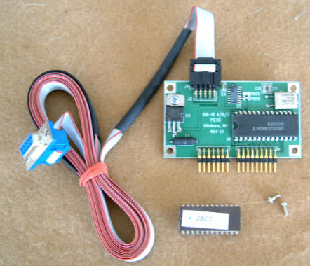
PIEXX offers
a snap in replacement for the old IF-10A, that not only
does the job of the original, but eliminates the need
for an IF-232C. This is the route I took for this radio.
This kit includes the required ROM chip, and installs in
the same manner as the Kenwood factory unit, except for
the method of cabling to the computer.
Where the
Kenwood factory unit requires the IF-232c outboard box,
and a pair of cables, the Piexx unit is able to directly
connect to the computer RS-232C port. It does this via a
5' ribbon cable with a D9 connector, connected directly
to the card. This connection lacks the elegance of the
original six connector jack of the IF-10A; but this is
more than made up for by the comparative ease of
installation. The interface costs just shy of $100. Even
so, when compared to the cost of an IS-232c, an IF-10a,
and the required cables, it is a bargain. Even so, this
is only half of the complete solution.
A signal
interface completes the package, and allows the radio to
do FSK, fax, and make use of various other digital
modes, both to encode and decode. It can even get you
SSTV. This is accessed through the ACC2 connector at the
back of the radio. This is a thirteen pin connector. A
mating plug is included with the radio, and is also
widely available. With this plug, a signal interface can
easily be made which will connect through a computer
sound card. Such an arrangement would also permit
logging and even recording of messages.
Many sound
cards have multiple inputs (usually a line in, and a
microphone), which allow for connection to more than one
radio at a time, though signal levels may need to be
adjusted. For connection to more than two radios, you
will need to install a special sound card with multiple
inputs. These are designed for home recording studios,
and are a bit more costly than normal sound cards,
though you are still only talking $100 - $150 for a nice
sound card (better than the one you already have) that
will permit connection of up to four radios. If you want
to keep your current sound card, an add on card with an
extra pair of inputs and outputs can usually be found
for $50 - $100. Cards with breakout boxes can have
input/output connectors for up to eight radios.
Once the
cards and connections are in place, you will need
software. There are a number of packages in place for
computer control of your radio, and countless programs
for packet, FSK, and various digital modes. Once you are
connected, a whole new world opens up. I am putting
together a page about the various bits fo software, the
digital modes available, how to use them and what they
sound like over the air. For now I recommend simply
doing a search on radio digital modes, and on ham radio
software.
As
with most commercial ham radios, there are a number of
modifications
and enhancements that can be made, many by the owner.
There is not a real wide selection of mods for this
radio. the most common are to change the 4800 baud data
to 9600, and various mods to enable transceivers made
for one area to use those of another.
Extended Transmit Frequencies:
-
Remove the top cover and locate the control unit (X53-1410-XX)
-
Cut diode D30, xmit now 430.000 TO 450.995 MHz.
The final output transistor is a Mitsubishi M57745, rated capable of generating up to 33watts on frequencies from 430 MHz to 450 MHz. A look at the trends in the data sheet indicate that the unit should have no problem getting down to the 420 range, if properly tweaked.
These units are also capable of taking optional boards to
give tone capability, voice announcement of operations,
and computer control.I will go into mroe detail on these
when I have time to update.
Updates
are
coming
The most significant mod is to change my D model Japanese spec radio over to an A model America spec radio. Details on this project are in the following section. The outlook is hopeful.
Using the
D model in The United States
This section will be updated
as soon as I attempt modifications.
The version of the TS-811 radio that I have is the D
version. This is the version meant for Japan, and other
parts of Asia. The radio is configured for the standard
United States repeater splits, and use of PL (CTCS)
tones; but is only able to access frequencies from 430
MHz to 440 MHz. The European E model is even worse,
having a similar limit of frequencies, but also being
set up for a 1.6 MHz split, and tone burst. I am a bit
hamstrung, using this radio in my area, since all of my
local repeaters operate above 440 MHz.
 One feature that the Asian model has, that I do not see
on the other versions, is the DCS system. It is similar
to the privacy codes now being used on many FRS and GMRS
radios. The feature is kind of pointless these days, but
it is an interesting curiosity. A number of PS/PB radios
use such things as calls for specific users. For this
type of user, where you have a dispatcher and a number
of mobiles, this can be very useful. For the amateur
operator, I see little utility. The system will only
work with another similarly featured radio. This is the
only outward identifying mark on these radios. They have
a reset button and an indicator for DCL. This is not a
feature that I am ever likely to use, but you never
know.
One feature that the Asian model has, that I do not see
on the other versions, is the DCS system. It is similar
to the privacy codes now being used on many FRS and GMRS
radios. The feature is kind of pointless these days, but
it is an interesting curiosity. A number of PS/PB radios
use such things as calls for specific users. For this
type of user, where you have a dispatcher and a number
of mobiles, this can be very useful. For the amateur
operator, I see little utility. The system will only
work with another similarly featured radio. This is the
only outward identifying mark on these radios. They have
a reset button and an indicator for DCL. This is not a
feature that I am ever likely to use, but you never
know.
The radio I
have also included an original paper manual, in the
original Japanese. I have included a link to the PDF of
the English manual for the TS-811A. The problem with the
Japanese manual is that I do not read Japanese, and I
can find no English translations of the D manual
anywhere. The radio certainly has a slightly different
layout than the American version, and I would be
interested to know how the DCL works. I would also like
to know a bit more about the internals of this radio.
Though the board is the same, it is configured quite
differently from the more well known American and
European models.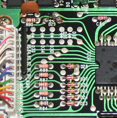
 My biggest concern with this radio was the
possibility of opening up the unit to operate up to 450
MHz, and maybe even down to 420 MHz. On the E and A
models, the range can be opened up by cutting diodes D30
and D34. Cutting the D34 diode on the E model will open
it up to 430 MHz to 450 MHz. Cutting the D30 diode on an
American (or Americanized) version will open up the
operating range a bit more.
My biggest concern with this radio was the
possibility of opening up the unit to operate up to 450
MHz, and maybe even down to 420 MHz. On the E and A
models, the range can be opened up by cutting diodes D30
and D34. Cutting the D34 diode on the E model will open
it up to 430 MHz to 450 MHz. Cutting the D30 diode on an
American (or Americanized) version will open up the
operating range a bit more.
The problem with the D version, is that these diodes are not even installed. This portion of the board is blank, though the positions of the diodes are marked. A photo of the board as it came is shown to the right. The empty solder pads for the diodes are at the top of the photo.
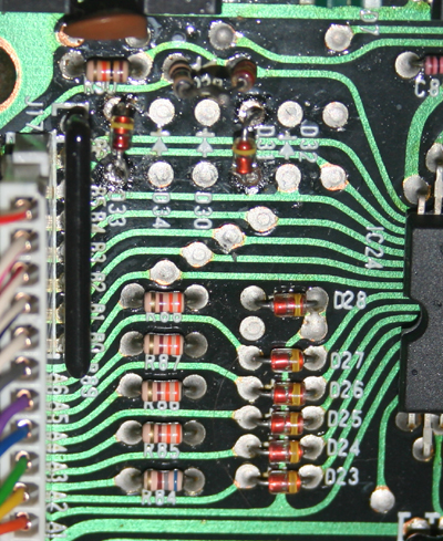
I could not resist the temptation to install the missing diodes (leaving D30 and D34 out), despite the fear that I might ruin my radio. The diodes that appear to be the ones that need to be installed are D30, D31, and D33 - though as I mentioned, I may leave D30 out.
The diodes used on the board are switching diodes. I was
unable to find these locally. The model number is
1SS133. These are rated at 80v 130ma. I picked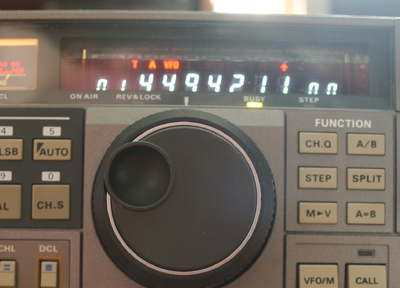 some up on eBay for about ten cents each.
I saw these same diodes selling for much less at various
electronic supply houses, but the orders generally had
to be for dozens or hundreds of units.
some up on eBay for about ten cents each.
I saw these same diodes selling for much less at various
electronic supply houses, but the orders generally had
to be for dozens or hundreds of units.
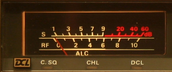
A photo of the modified board with the new
diodes installed is to the left above. Please, no
comments on the quality of my solder job. I am not an
electronics tech. The job is good enough, despite
appearances, and the radio will now tune up to 450
MHz, as can be seen in the photo to the right. Or can
it? Installing the diodes enables the processor to hit
frequencies up to 450 MHz; but things are a bit more
complicated.
It is also necessary to recalibrate or retune
certain portions of the radio, and to open up the
front end. While cutting and jumpering diodes may open
up the processor and mixer, the coils and other tuned
circuits may need to be opened up as well. In the E
version, opening the frequency range also requires
retuning and calibration. Without doing this, the
radio will be deaf on the extended frequencies.
In particular the two helical filters must be
recalibrated. In order to be done properly, an
oscilloscope and a special connector (which can be
easily home brewed) are required. The helical filters
are there to remove spurious signals and possible
harmonics. They can be adjusted with a screwdriver. I
have included a
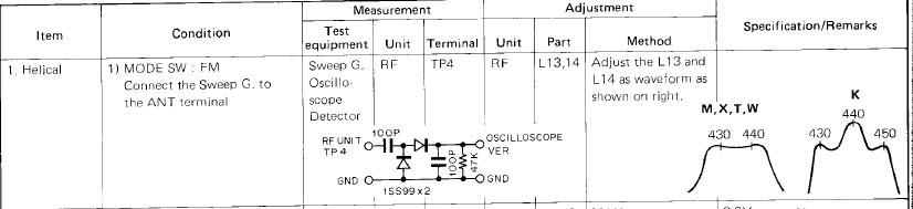 cropped scan from the
service manual, advising how to calibrate the filters
for various versions of the radio. In theory, I
suppose you could just open them all the way; but this
will certainly cut down on the cleanness of the
signal. Adjustment of the filters allows for operation
on the full band with a nice clean signal.
cropped scan from the
service manual, advising how to calibrate the filters
for various versions of the radio. In theory, I
suppose you could just open them all the way; but this
will certainly cut down on the cleanness of the
signal. Adjustment of the filters allows for operation
on the full band with a nice clean signal.
My big worry
now, is that the unit produces frequencies between 430
and 440 using the PLL, and from 440 - 450 using a
crystal based oscillator. It is my hope that the crystal
for the higher frequencies is installed for consistency,
and will be available after the modification. Otherwise
the project is going to get very complicated. I have
read of no such issues with the European units; but the
Japanese unit may be different.
The only
other real concern on this version of the radio is the
power supply. The Japanese version requires up to 8 amps
of 100 volt AC. This is pretty close to the American 110
- 120 Volts, so I am not too worried, but it is a
consideration. The radio appears to be operating fine.
If worse comes to worse, I can always operate it
directly on 13.8 volts DC, but so far this has not been
necessary.
This is not
something that I would recommend, for the person simply
looking for a great 440 radio. It has become quite the
project, and the Japanese version is not any less
expensive than the corresponding American or European
versions. If nothing else, this gives me a chance to
learn, and to play with the insides of yet another
radio. It will also make my shack just a tiny bit
unique. How many operators in Wisconsin have a Japanese
version of a 70 cm radio? I suspect not too many.
The diodes
used on the board are switching diodes. The model number
is 1SS133. These are rated at 80v 130ma. I picked some
up on eBay for about ten cents each. I saw these same
diodes selling for much less at various electronic
supply houses, but the orders generally had to be for
dozens or hundreds of units.
 band can be six inches high.
A beam can be a couple of feet long, and a J-pole or
Slim Jim can be less than two feet long. My first
antenna for this radio was my old magnet mount 440,
mounted to a metal plate. This was for testing purposes
only. I also ran it for a bit on the copper Slim Jim for
2 meter, as the bands are resonant with each other.
Still, for best efficiency I really needed an antenna
tuned to this band. In addition, using a 2 meter antenna
for 400 gives a pattern that is a bit too high for my
tastes.
band can be six inches high.
A beam can be a couple of feet long, and a J-pole or
Slim Jim can be less than two feet long. My first
antenna for this radio was my old magnet mount 440,
mounted to a metal plate. This was for testing purposes
only. I also ran it for a bit on the copper Slim Jim for
2 meter, as the bands are resonant with each other.
Still, for best efficiency I really needed an antenna
tuned to this band. In addition, using a 2 meter antenna
for 400 gives a pattern that is a bit too high for my
tastes. Because they can be made so small, I have also built a horizontal dipole, and a beam for this unit. In addition, I am putting together an experimental cobweb antenna, to test the concept for a possible future HF antenna based on this design. The cobweb element for this radio would be three inches to a side. This is the one radio for which I have considered the construction of a beam.
The disadvantage of this frequency is that it is badly attenuated by most building materials. Where HF will usually not be much affected by indoor installation, VHF, and especially UHF, can have absorption and attenuation issues. It is best to have these little antennas outside. It is also very susceptible to feedline loss. RG-58 cable has 10db loss per hundred feet. RG-8 has about 5db loss per hundred feet. Even 300 ohm ladder line, which usually has what is considered to be negligible loss, will have losses of about 2db per hundred feet. So in addition to having antennas outside, the antenna should be very close to the transmitter. Sometimes these two requirements are contradictory. The upside of this is that because the antennas are so small, it is easier to put an unobtrusive antenna outside.
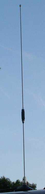
My main antenna for this radio is a Slim Jim. I have made this from soft copper tubing, and have it hanging from the wall of my shack, very near the radio. It is approximately 18 inches long. I also have a horizontal dipole, which was also made from soft copper tubing. I am presently getting my feet wet in antennas design, and have a five element Yagi (my first), and a loop (also my first). What is great about this is that these experiments do not cost much, and can easily be discarded if they are not suitable. Summaries of my 70 cm antennas are below. Details are on my antenna pages.
Though this is my least used radio, it has more antennas than any other radio I own. the temptation to experiment is just too great. I am hoping to do some experimentation with loops, spirals, and helical antennas as well. Such shortening techniques are not even remotely required at these high frequencies; but they are easy to build, test, and compare. I have even made a small wire slim Jim for a handheld and mounted it in a length of PVC, soldering it to a BNC connector. It works quite well, and I would never have considered doing such a thing on two meter. For mobile use, I still employ the classic magnet mount antenna, using the car body for a ground. Interestingly, this is inferior to my little eighteen inch J-pole, so perhaps a little experimentation is required here as well.
Slim Jim
The Slim Jim is a vastly improved variant of the classic J-pole antenna. It is a groundless vertical antenna with 6 db gain, and a very narrow horizontal beamwidth. This is my very favorite antenna for VHF/UHF FM use. The only reason I do not have Slim Jim antennas for all of my bands is the very large size of this antenna. These are basically three quarter wavelengths long, though their groundless nature means they can be quite narrow.
Functionally, a J-pole is an end fed vertical dipole, with a quarter wave matching stub. A Slim Jim is the folded version. The Slim Jim is often preferred for its larger bandwidth, and flatter radiation pattern. The matching stub is used to prevent pattern changes by proximity to ground. A pure vertical dipole would be very much affected by height. There is not exact formula that can be given for such an antenna, due to variation sin install locations. The most important consideration is the location of the feedline connection along the matching stub. This offers the advantage not only of matching the antenna to the location, but also of matching the antenna from variances in construction. Distance between elements, width of elements, and length all interact in these antennas.
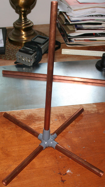 Ground Plane
A classic groundplane was easily made in about an hour, from five 6" lengths of copper pipe. Though this was a satisfactory antenna, it offers no gain, and can be a bit cumbersome with the four radials sticking out the bottom. This antenna has been retired to the attic, where it serves as my GMRS antenna. There is nothing exciting or unique about this antenna. Along with the horizontal wire dipole, the classic ground plane is common and known to every novice.
On such high frequencies, an antenna made from half in pipe, as this one is, has a fairly high bandwidth. At GMRS/440 frequencies, a half in pipe is something like 10% of a quarter wave. This is great news, for a couple of reasons. It partially compensates for the high losses at these high frequencies, by keeping sir low. It also also allows for effortless tuning, without the worry of antenna tuners.
Such antennas are so simple, that they have even been made by soldering wires to the mounting holes of coaxial connectors, along with a copper wire in the center position to act as radiator. Such an antenna lacks the higher bandwidth of the copper pipe version, but can be made for a few dollars.
Beam antennas are not usually an option for the apartment dweller. UHF is an exception. I have easily put together a five element beam, which is small enough that I can hold it in my hand and aim it out the window. Such small beams are often used with hand held radios to chase satellites, meteor scatter, or auroras. I am considering mounting this on a gun stock, though with all the paranoia in the world today, I am not certain this will not attract the attention of nervous police officers - maybe of I paint it orange.
This antenna, in common with the one below, is of wooden construction, except for the elements. It has a single active element, with a pair of directors in front and a pair of reflectors in the back. It should get me something like 12 DB gain, though I have no way to test this.
Mini cobwebb
This has been a great help to me looking after design considerations for my HF Cobbweb antenna. it is also a pretty good antenna in its own right. Even so, this is not a real practical antenna for use on UHF, due to its horizontal polarization. Nearly all UHF communication is local FM, usually through repeaters. Skip, on anything other than meteor scatter, Moon bounce, Auroras, or satellite is nearly unheard of at these frequencies. The mini cobbweb is for use on 70 cm, 220, and 2 meter. It's a shame we don't have 4 meter amateur here in the U.S. It would make for a nice balanced antenna. Six meter is just too far away, so this will be a three band cobwebb.
| Band | Side | Wire run | Construction is easy, due to the
small size of the elements. This will be the
common horizontal antenna for all of my VHF/UHF
radios. It is small enough to be used vertical
and aimed for RDF. More details latter. Measurements given are approximate, before trimming. I used double stranded speaker wire in construction of the radiators. The framework is a simple X of wooden dowels. Wires were all joined at a common feedpoints, and then soldered to the coax connector. Shorting points are determined by trial and error. These are necessary to adjust impedance. Natively, the antenna has an impedance of about 12 ohms. Shorting the twin strands and reversing them quadruples the impedance to around 48 ohms, nearly ideal for coaxial connection. |
| 440 (70 cm) | 3" | 12" | |
| 220 (1.25 M) | 4.5" | 18" | |
| 144 (2 meter) | 9.6" | 38.42" | |
Links
Not much out there, as the 70 cm band is not really a popular band for base operation. Still, the radio has a following, and has generated a certain amount of interest.
| eham review | TS-811 user group | Radio facts. | Service manual |
| http://jh1lkj.blog.ocn.ne.jp/blog/2011/05/ts811d_9035.html | |||