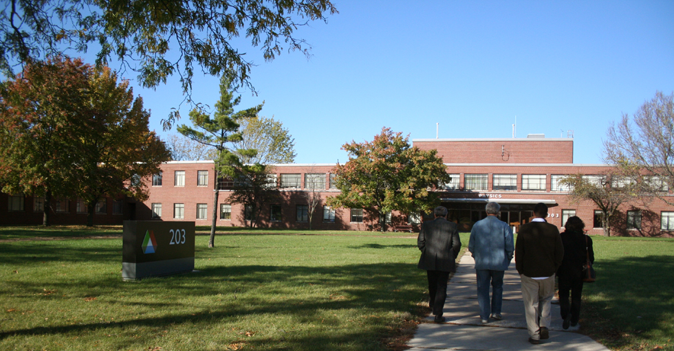
ATLAS
Lowell Bollinger's giant, upon whose shoulders we attempt to get a better view of the universe. Though such a machine has the potential to do many things, it's primary use seems to be to create isotopes that do no exist in nature. Our guide showed us a chart, listing all of the elements, and all of they known isotopes. He advised us that many of the experiments carried out there, have a goal of enlarging this chart, and of making it's entries more complete.
Lowell Bollinger's giant, upon whose shoulders we attempt to get a better view of the universe. Though such a machine has the potential to do many things, it's primary use seems to be to create isotopes that do no exist in nature. Our guide showed us a chart, listing all of the elements, and all of they known isotopes. He advised us that many of the experiments carried out there, have a goal of enlarging this chart, and of making it's entries more complete.
 |
|
 |
|
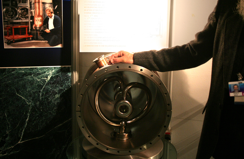 |
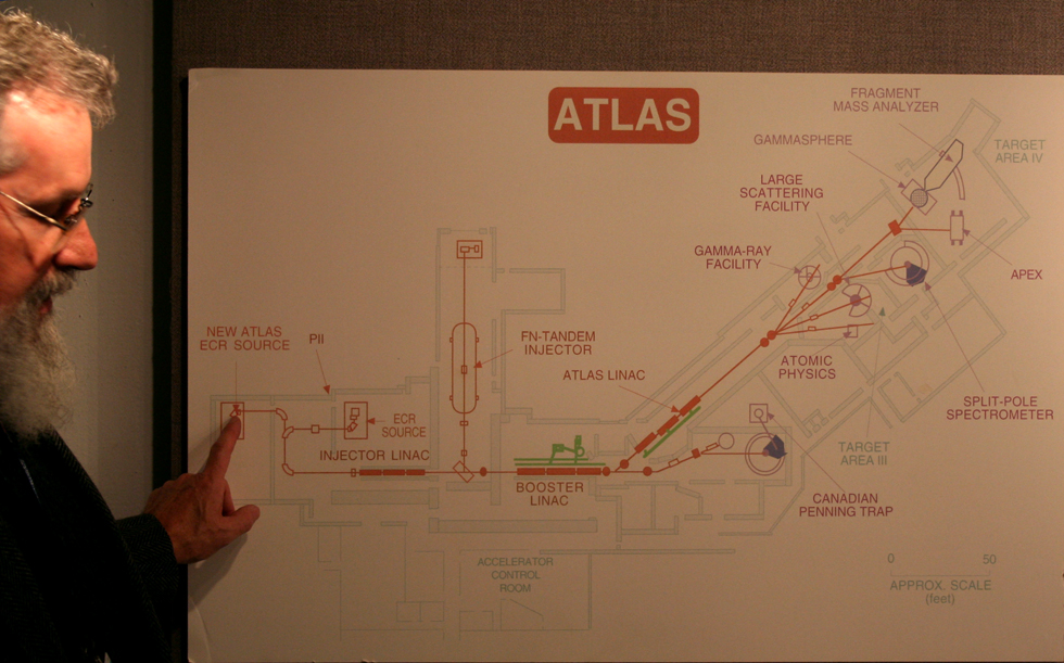
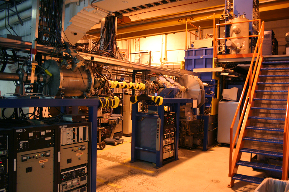
Above: A diagram of ATLAS, as it stands today. The unit began much smaller, and future plans have it growing much larger. Left: An open view of the heart of the system, a Superconducting Split Ring Resonator. These are constructed of niobium, due to this material's superior superconducting abilities at comparatively high temperatures (though it is still pretty cold). Ions are pumped through the center, by an alternating current. The current frequency is in the same range as that of the FM radio band. |
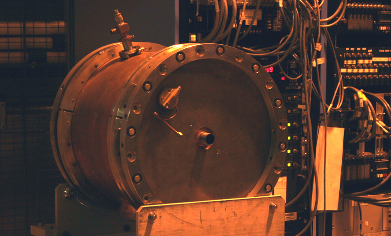 |
A photo of the Superconducting Split Ring Resonator, fully dressed, and ready to be installed. The outside of the ring is coated with copper, though a unique process where it is blasted on by dynamite. the nozzle near the top of the drum is for the introduction of the liquefied gas which cools the unit down. |
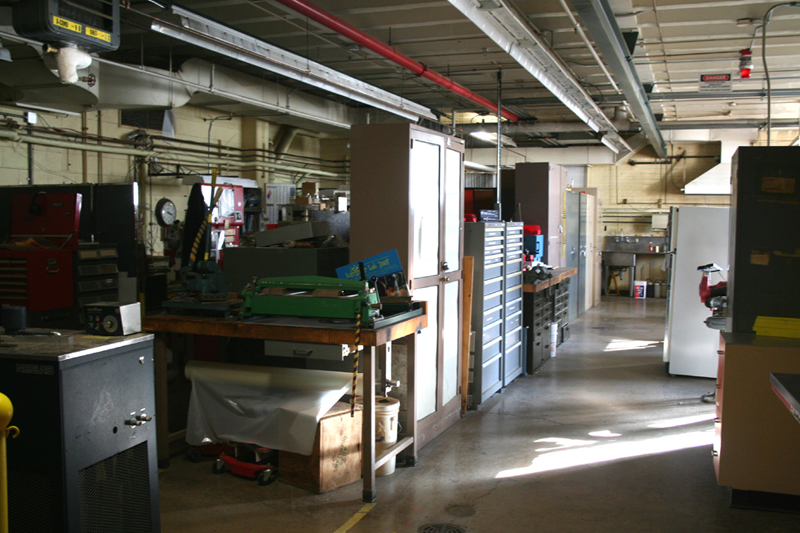 |
One of the many workshops and repair shops in the building. Many, if not most, of the components of these machines are custom made, right on the premises. You can not exactly order a split ring resonator out of a catalog. If something breaks it must be repaired, or remade, right here. |
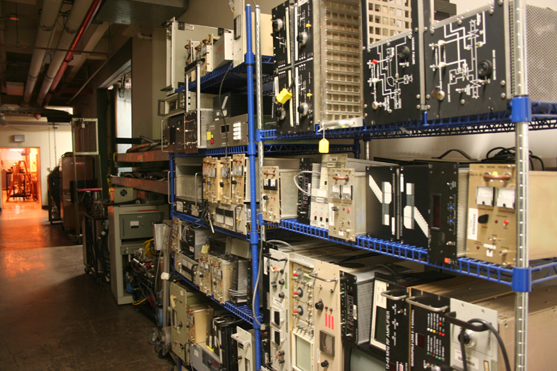 |
Left: Some of the instrumentation awaiting experimentation. The other side of the hall holds spares. Researchers wait for months, sometimes for years, to get a few hours time on one of the machines here. They must be kept in constant service. Below: The ion source. This is the ECR unit which provides the stripped down nuclei, for the accelerator. |
 |
|
 |
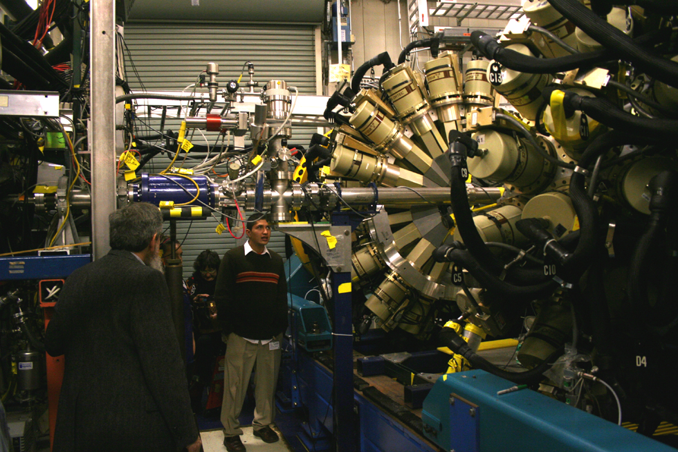
Our guide showing us a section of the beam tube (actually a part of the injector). A narrow beam of accelerated atoms travels though a vacuum, at a healthy speed, approaching that of light. The ECR is just out of sight, to the left of the photo. |
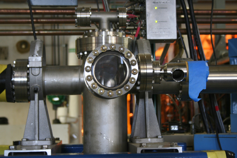 |
A window into the beam tube is tightly closed up by a ring of bolts, in order to retain the vacuum of the tube. Though the beam itself is invisible, instruments placed within the window can measure it's passing. |
 |
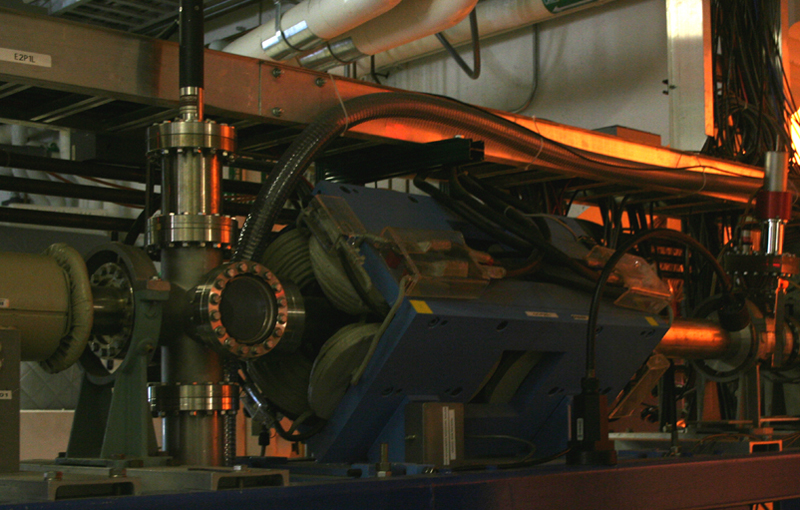
A magnet at one of the elbows of the tub, acts as a filter, for stray atoms. No sample of material is absolutely pure, so a few bits of contamination may be present. A properly set magnet will bend the paths of the selected element just the right amount. Lighter or heavier elements will either curve too much, or too little, colliding with the walls of the tube. |
 |
|
 |
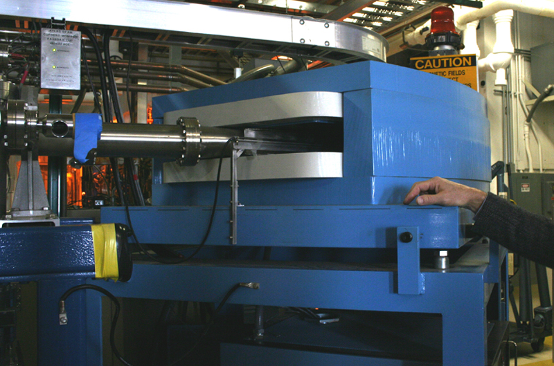
A beam straightener. Our guide explained that the beam tends to get wider, and can some times angle. This special magnet keeps the beam straight and narrow. |
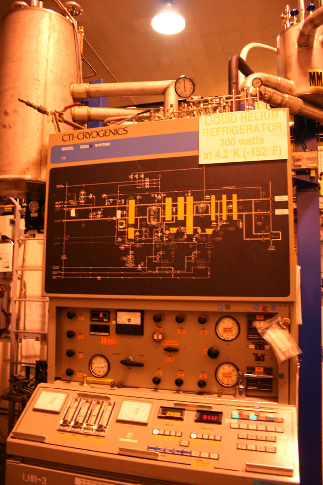 |
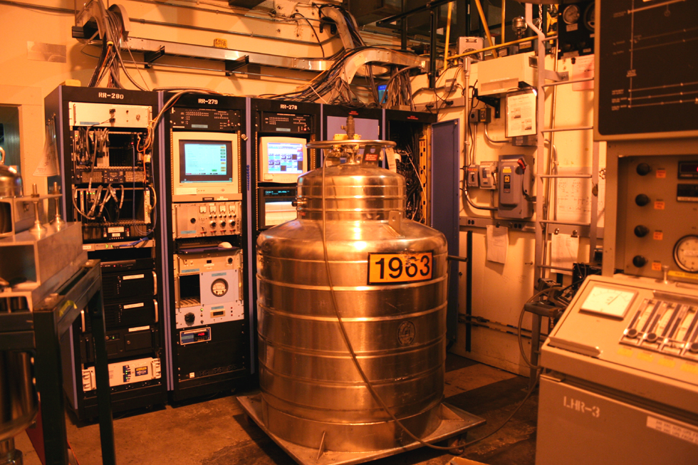
Left: The console for the cooling system, Note the temperature displayed on the placard --- -452 degrees. Below: A bit more of the cooling system , as well as a tank designed to hold liquefied gas. Behind the tank are the usual consoles, instruments and controllers which seem to fill every inch of space here. |
 |
|
 |
|
 |
|
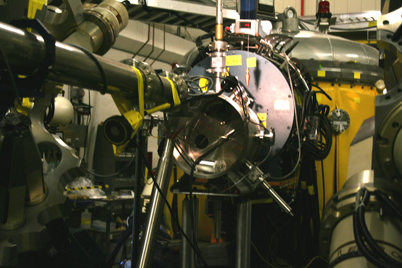 |
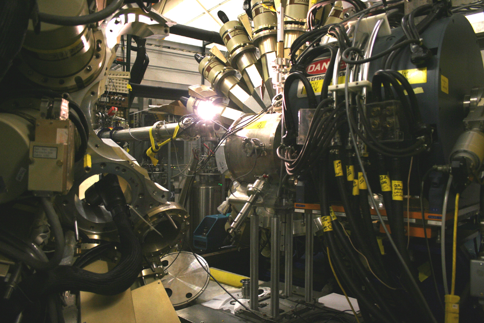
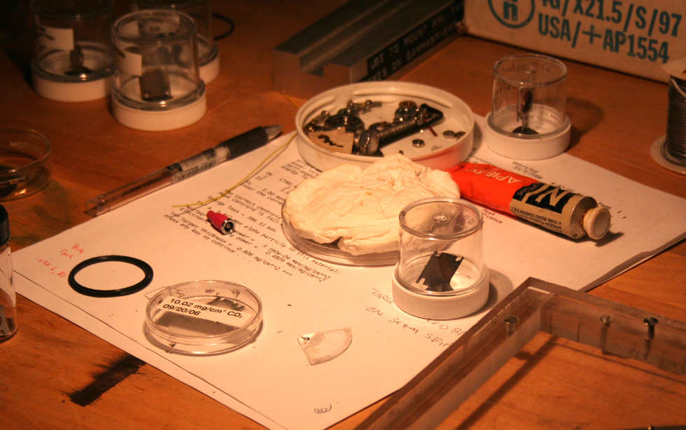
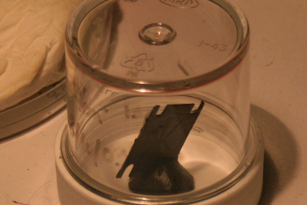
This is the gamma ray facility. When
electrons get excited, change energy states, or wiggle around,
they give off photons, in the form of visible light. This is how
light bulbs work. When protons and neutrons do this in the
nucleus, they also give off photons, though with much more
energy, as gamma rays. When atoms get smashed, they give off
lots of gamma rays, which are gathered, measured, and looked at
by the instruments here. The units are separated in these
photos. In use, they would be pushed together, around the beam
tube shown at top, to surround the target. The center photo
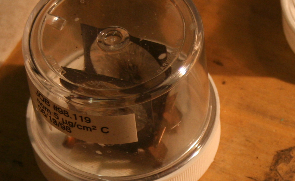
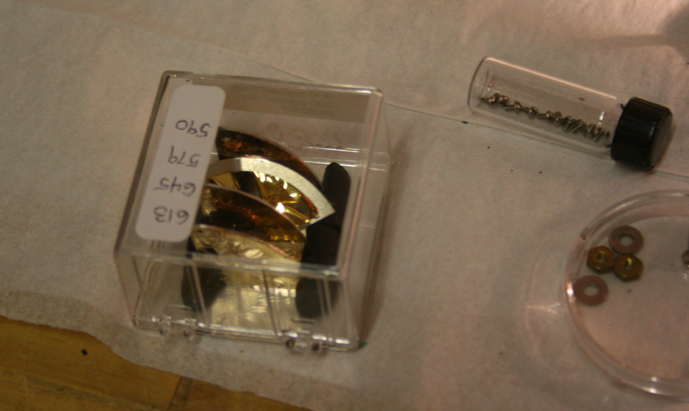
shows the target area. Far below: The last several photos in this section are of various targets which have been hit by the beam. |
 |
|
 |
|
 |
|
 |
|
 |
|